
 An 80 through 10 meter Ground Plane

The HF Ground Plane Antenna System employed at
WD4NKA.
I have been asked several times on the various FaceBook groups that I am party to regarding details regarding my roof mounted Vertical. Rather than take up space on the several groups, I thought it more convenient for the reader... and more efficient... to simply write a blog entry and refer those interested in this antenna to this installment.
Firstly, the antenna itself is what I might call "Garden Variety". You can find it in the antenna section of any Amateur Radio Handbook, going as far back as nearly a century. A quarter wavelength vertical element and a counterpoise, normally a parallel connection of quarter wavelength (or 5% over) radial wires.... or tubing.... depending on the antenna dimensions.
Almost like an Inverted Vee on it's side. The feed point is at the high current / low voltage node of the emitted wave assuming a quarter wavelength per "side", just as a center fed half-wave dipole. A low impedance feed point, only unlike a dipole, something less than a balance feed. This is why baluns, while frequently used for center fed dipoles when using unbalanced coaxial feed... are not usually used to feed verticals. At least, not the quarter wave verticals I've read about or have built, or have seen mention of in the construction project instructions.
When a vertical is elevated from the ground, and it's radial "counterpoise" system likewise raised, the losses caused by earth is greatly reduced; fewer radials are required to sustain a decent counterpoise, sustaining a lower angle of radiation. Various research papers indicate that as few as four, three, and in one case only two radials are needed for proper function of a raised ground plane. Indeed, my memories of the half wave and 5/8th wave ground plane antenna systems popular with the CB community for decades bare this out. Most only had three radials.
Ground mounted verticals popularly had a requirement of 120 ground radials cut to 5% over quarter wavelength (or so). An elevated ground plane system does well with radials cut right to a quarter wave. In my opinion, an added 5% of length has really no bearing. I've used both. No difference.
My own Ground Plane is made Quarter Wavelength to 40 meters, employing a vertical element of 33 feet, with 33 foot radials. The vertical element is made from telescoping aluminum tubing, the radials of insulated 14 gauge stranded copper wire. I use five radials for 40m, and after about a year of experimentation, an extra addition of 3 to 5 radials cut to about 70 feet for use on 75 meters, wherein this antenna becomes a 1/8th wavelength ground plane at 75 meters. More on this later.
Having used this scheme for decades, usually using used tubing from former antennas, I found that the windage normally experienced during our summer "monsoon" season induced a great deal of stress on my 33 foot "Space Needle" bolted to the gable end of the house on a push-up pole, and after about 20 years, it finally bent over during a tropical storm. It took that long.
In 2019 I decided to rebuild the "Space Needle", as it is affectionately known in the neighborhood. Only this time all new aluminum would be used. It would be re-enforced, and it would be very, very secured.

This is the scale rendering I made on Macromedia "FreeHand", my fav vector IDE. What you see is a 33 foot telescopic pole bolted to about three feet of mast using four saddle clamps. A weatherproof gasket sealed aluminum box is also clamped to the antenna base serving as both a place to mount an SO-239 coax female jack, an insulated stand off to run a wire from the antenna base to the coaxial feed. It would also serve as common to the coaxial ground, where the radial wires would ultimately be attached. And so the parts were ordered, largely from DX-Engineers.
Also shown in the above drawing is a Sched 40 PVC pipe covering all but about a foot of the bottom tube, which is 1.5" in diameter. There are end-caps at each end of this PVC pipe, the top cap being drilled out to 1.5" for the base tubing, the bottom being drilled with a small hole to permit condensation to escape, a "weep" hole. The feed wire would be drilled through the base of the PVC pipe above the bottom end cap, and into the base tubing itself.
The purpose of the PVC is to help absorb the torque developed as the antenna flexes in the wind, and I have seen these antennas endure sustained 75-85 mph winds and higher gusts. This re-design and "build" would be a bit stouter than my prior verticals, six telescoping 6 ft. lengths, the bottom tube being 1.5". This makes for a fairly stout 33 foot extension with three feet of interplay between the tubing sections. The greatest interleave is on the lowest and second to the lowest tube sections, decreasing toward the top.

This is the vertical when I had just put the tubing together and prepared the PVC and end-caps. The saddle clamps are made from red oak, soaked in varnish and dried, about a three day process. This shot shows the assembly bolted to a length of 1.25" diameter mast, used to "try" the U-clamp and Saddle assembly. It was kind of tricky drilling out the saddles.

Here is a closer look at the four saddle clamps. These oak saddles lasted about three years, and actually could have lasted longer had I not chosen to rebuild this antenna this summer (2022) I had chosen to rebuild not for any flaw in the design electrically, but for construction and structural improvements. This year, 2022, is projected to be an active hurricane year, and this antenna is heavy. Too heavy for me alone to unbolt and lower.... then raise again several times in a season. As such, the four-bracket bolt up seen here, although very successful, was destined to change. But the antenna electrically remained the same.

This is a close-up of the top section of the PVC, showing the method I used to clamp the telescoping sections together. I think the six 6-foot length of tubing cost about $125.00 in 2019 when I ordered them from DX-Engineers. That price has gone up, but I would do the same today despite the cost. When you used new parts and quality stainless hardware, there's a lot less to worry about.

This is a view of the vertical as it appeared in June of 2019. Note that there is a coaxial RF choke in series with the feed. This knocked out a lot of RFI. The weatherproof aluminum box was not used at this point, a direct feed to the antenna base was used. That aluminum box made it's appearance when I placed a coil in series with the feed to bring the swr down for use on 75 meter AM. The introduction of that coil, and this antenna's use on 75 meters is a story unto itself, but that can wait for another time.

This is the grounding plate that I used for the first rebuild, and still use today. A total of ten radials, six for 40m and four for 75m fanned out across the roof, from west to north to east. The feed point is approximately 18-20 feet above average terrain.

Here is a shot of the aluminum box with the 75m series coil. At first I used a switch to select 75m or 40m and higher.... but the feed point at 75 meters, using a few hundred watts on AM develops a high voltage, and soon the switch burnt out. So I took this switch out and replaced it with an insulated stand-off connect as is on the top of the box. I unscrew the wire coming from the antenna base from one ceramic stand off (with a stainless screw and wing-nut) - and bolt it up to the other, depending on the band. This requires me to climb the "crows nest" each time I change from 75 meters to 40 meters (and higher). Actually..... I like it that way. It allows me to inspect the antenna each time I ascend the Crows Nest!
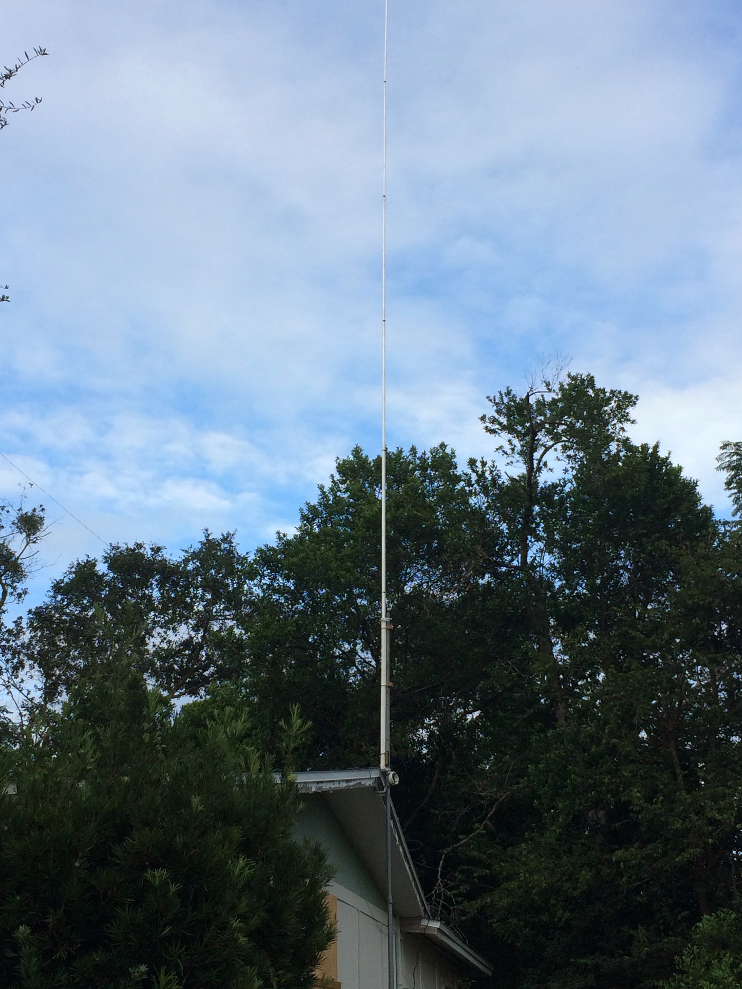
This was the "Space Needle" from 2019 to 2022. And it performed very nicely, resonant to 40m and 15m naturally, and using a tuner for 20 and 10 meters easily. On 75m, the coil brings the standing wave down to about 1.7 or 1.8:1, the residual reactance is tuned out by the antenna tuner, a Dentron MT3000A.
This year (2022) is projected to have an active hurricane season, and frankly, I'm getting too old to lug this beast up and down the roof each time a hurricane threatens. Thus it was determined to change the mounting system to the mast, and while at it, replace the mounting hardware with stainless all around, and also re-enforce the gable fascia, and double the brackets holding the push-up pole. The new mounting system would have a stainless pivot mount instead of the saddle brackets, a stand-off brace would provide the extra bracing at the four foot level of the base of the antenna, providing less coupling between the vertical radiator and the mast.

This is the new hardware used in the re-build of my ground plane. New 14g insulated stranded wire for the radials, new stainless brackets (DX Engineers), new pivoting mounting bracket (also DX Engineers) and also not shown: new eve brackets for the mast. It took about two months to gather everything together, and meanwhile the vertical came down, everything inspected to make sure all was doing well with the vertical itself. The radial mounting plate was cleaned and polished. New Y-lugs for the radials were obtained. Also the weather proof aluminum box holding the 75m matching coil was re-fitted with stainless connecting hardware.
Essentially everything stayed the same electrically. It is the same ground plane, only with better hardware and a pivoting mounting bracket to make lowering the antenna in case of a hurricane easier for an old guy like me. I think the photos below will tell the rest of the story:

The new mast mount: the gable fascia was doubled for a more secure anchoring of the mounting hardware. a lower bracket was added, and new stainless U-clamps were installed to better hold the mast in high winds. The mast itself was sunk about 3 feet into the ground, and grounded using a series of 6-foot copper ground rods, also used to ground the station equipment.

This is the 75m matching coil and switching box. The coaxial RF choke is mounted below the antenna feed.

The four saddle brackets were replaced by a combination of the pivoting base and the stand-off clamp at the four foot level. (photo shot before the 75m coil was mounted.)

This is a closer look at the base and stand-off clamp. I was in the process of installing the switch box when I took this shot. The 40m radial wires were also laid out after this photo was taken.

A photo of the re-installed radial mounting plate. This plate holds ten radial connects. Five are for 40m, the remaining five will be for 75m. Or.... I may do six for 40m, and four for 75m, depending on how much wire I have on the spool (500 feet.)


And here you go! The last three shots pretty well sum up the project. Preliminary testing on 40, 20, 15 and 10m show that everything is operational. I have yet to lay out the 75m radials, but that will happen the next rainless- thunderstorm-less day I have off to work on it. Hopefully by August. It's good to have the "Space Needle" back up again!
de wd4nka
Deltona, FL
SW Volusia Co.
No comments:
Post a Comment