All Things Wireless & Letterpress

All Things Wireless & Letterpress

Monday, May 16, 2022


Gary's Awesome Adventures in Amplitude Modulation (AM Radio Transmission & Reception) :

Prepping the Johnson Viking Ranger for Station Use, Part 4. 


There are a number of reasons to install a PTT (Push To Talk) relay into a Johnson Viking Ranger, not the least of which is to save wear and tear on the "Operate" switch.  Without a PTT switch, it is, of course, possible to do AM phone, just rotate the switch between Phone and Standby.  And that will work.  However, these rotary switches were not meant for constant off and on operation!  They were designed to be positioned and parked for a while, like a band switch.  The original Potter & Brumfield relay switch was recommended by Johnson as the relay of choice, and recently I discovered that some Rangers actually came pre-wired for this relay.  Mine was.  Either that, or whoever did the wiring did an absolutely professional job soldering the wires in place, wrapped and taped the wires above deck near where the relay was to be installed in pre-drilled holes to place the mounting screws... but never actually installed the relay switch!!   The tape used to band these wires was yellowed and brittle with age, as if whenever the taping was done was about the time the radio was made.
 
Cruising about the internet forums informed me that indeed, some factory Rangers were, in fact, pre-wired.  That was news to me.  If anyone has documentation to this effect, please let me know at wd4nka@gmail.com.  I'll post the documentation to my blog.  Until then I will classify this bit of information as a definite maybe.
 
Potter & Brumfield relay switching aside, D-Labs has come out with a better solution that accomplishes two design goals: to provide a non-drill solution for PTT switching, and to solid-state the low voltage rectifier.  The wiring is at most at least as intensive as the original PTT wiring plan indicated on pages 19 and 20 in the Ranger Operations manual.  As it turns out, all but two of of wiring required for the K1 or K2 relay is already in place if installing in a pre wired Ranger such as mine, if yours is not, said wiring is not all that hard.  Only two solder points were actually challenging, but as I will share in this installment, there are work-arounds to make things easier.
 
First, let me share D-Lab's video covering the K1 installation.  This will apply to the K2 as well.  For what you get, they are well worth the money!


Terry's video shows the basic installation of the K1 relay.  Later, he produced the K2 relay, which is the same as the K1, with the same wiring, but the K2 provides for two more switch functions which can be utilized according to the installer's discretion.  You can key a transmit light, you can kill screen current in the modulators when the modulator is switched off, you can key an ACR, any number of things.
 
I purchased the K2 relay, although I had no immediate plans on how to used these extra relay ports.  Probably at a future date I'll look into keying an ACR, but the jury's out.  Maybe later I'll tackle that, but for now, I just wanted a PTT relay, and yeah, nice to reduce some heat by SSing the low voltage relay.  I am not very comfortable SSing the 5R4 HV rectifier simply because the components in place are designed around the voltage drop of this rectifier.  Since it is high voltage, and since there is little to no VR drop using silicon diodes, that B+ rail will be significantly higher.  It's not such a big deal with the low voltage rectifier.  So I opted to keep the 5R4 in place.
 
The next video is for D-Lab's K2 relay.  It's worth watching even if the basic rely wiring is identical to the K1.  Terry gets into what to do with the extra relay ports, which may spark some ideas.


Wish I could get my daughter to do one of my videos with me.  Oh, well......
 
Terry pretty much covers the installation, and I'll not repeat everything here in this installment.  What I have endeavored to do is address a couple snags I ran into.   Like I said, my rig came pre-wired for the Potter & Brumfield relay, which is close to the wiring of the K1/K2 relays.... but not identical.
 
Most of the wiring involves accessing the front wafer of SW4, patially above deck, partially below deck.  There are two black wires soldered onto clip 8 of SW4 (front) wafer... the wafer closest to the front panel, the one behind the (rear) wafer.  These are to be removed and soldered onto the black wire pre-wired onto the K1/K2 board.  These two wires were in fact removed, only in a rather round-about manner, and fed below deck where they were soldered together and covered with rubber tubing. Another wire was soldered to this joint and fed above deck, and taped off.   A wire ran from clip 8 of this same rear wafer, accessed from below deck, and fed back up above deck, wrapped and taped off.  I noticed that these wires, all black, were the exact same wires used for all the black insulated wiring done on this rig!  Clip 5 goes to the white wire pre-soldered to the relay board, and again, a black wire was already soldered into place, fed above deck, and taped off.  Wow, this was gonna be easy!  All I had to do was solder a wire onto SW4 (front)'s clip 8, run a wire from pin 2 of the mic jack (a cap to ground was already in place) to pin 4 of V-12, and boom!  Ready to go.
 
Then I looked at where this pin-4 was.  Hidden under that big log of a variable ceramic resistor (R35), and that resistor was bracketed into place, and the screws that held those brackets were danged near impossible to reach.  Since that resistor (R35) is pretty fragile.... I needed to think this one out.  Here's what resulted:


There it is.  R35.  One bracket behind a choke, the other tucked up under the lip of the chassis, where none of my tools could reach well.  The brackets are screwed through the rear apron of the chassis, through the bracket mounting holes, the lock washer and nut bolting up from the inside.  I did manage to get a needle nose in there to just loosen the nut from the inside, assisted by counter turning with a screwdriver the screw from the outside.  At length the screw came out, my finger keeping pressure on the nut so it wouldn't drop.  That pressure was enough for it to stick for a couple seconds on my finger, enough to remove it from the scene.


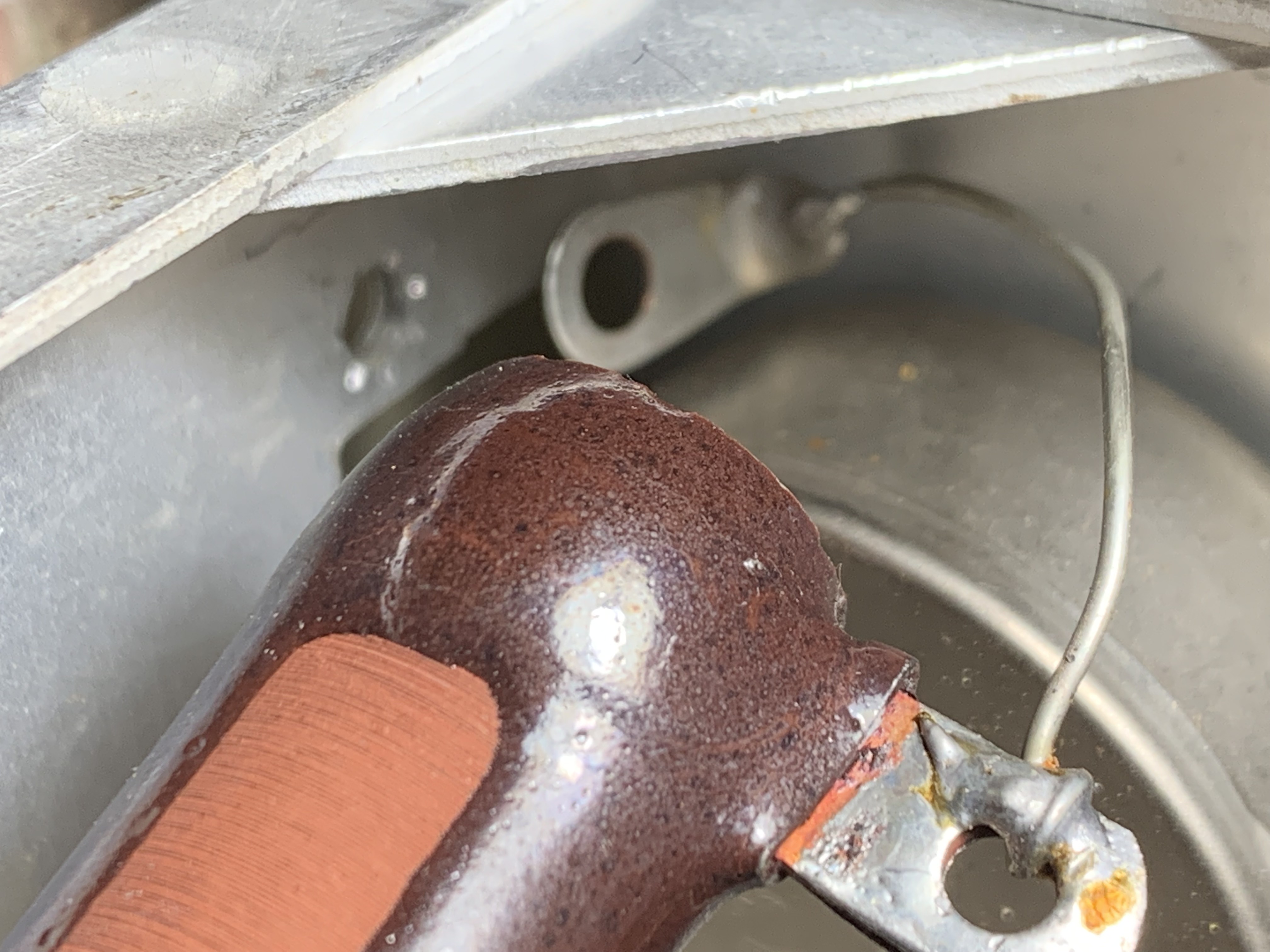
The screw was then pulled out from the back, and the bracket removed.  You can see that R35 is grounded at one end via a soldered eyelet that is held by the bracket screw.  No... the resistor isn't cracked.  Believe it or not, that line you see on the resistor is a reflection.  Trust me.  I had to look twice when I saw this photo on my I-Phone.  
 
One nice thing about these mounting screws is the use of lock washers.  On the other side of the resistor I could just turn the screw from the back of the rear apron, just enough to allow me to move R35 upward, and clear the way to access pin 4 of V12.


Here is a photo of R35, moved up just high enough to clear V12.  Even though things are still a little cramped, it was at least reachable by the soldering pencil.


Here is a close-up of V12.  Pin four is the vacant pin at the 1-oclock position, and is clear of anything soldered to it.  The wire soldered to it came from Pin 2 of the mic socket, and was threaded across the chassis to this point, as near to the chassis as possible.  It is the only really long wire run in the transmitter.  The task remained to put R35 back where I found it.  That wasn't going to be easy since the bolt is beneath the chassis edge-lip, inaccessible for any of my nut drivers and other handy tools.

I discovered that a wooden barbecue skewer could thread an 8-32  washer.  This would be what I would use to position the nut from the inside.


This solved the holding of the nut from the inside under-deck of the chassis, but the screw had to be re-inserted through the rear apron, and the resistor ground eyelet placed between the bracket and the nut and lock washer.


This was solved by taping the screw in place temporarily, for which I used both hands to hold resistor, bracket, lock washer, eyelet and nut in place.  The tape was subsequently removed after everything was tightened.
 
With the audio wire in place, I moved on to the last remaining wire pre-soldered to the K2 relay, the Red wire.  This would go to SW4 (front) clip 6.


Yeah, right.
 
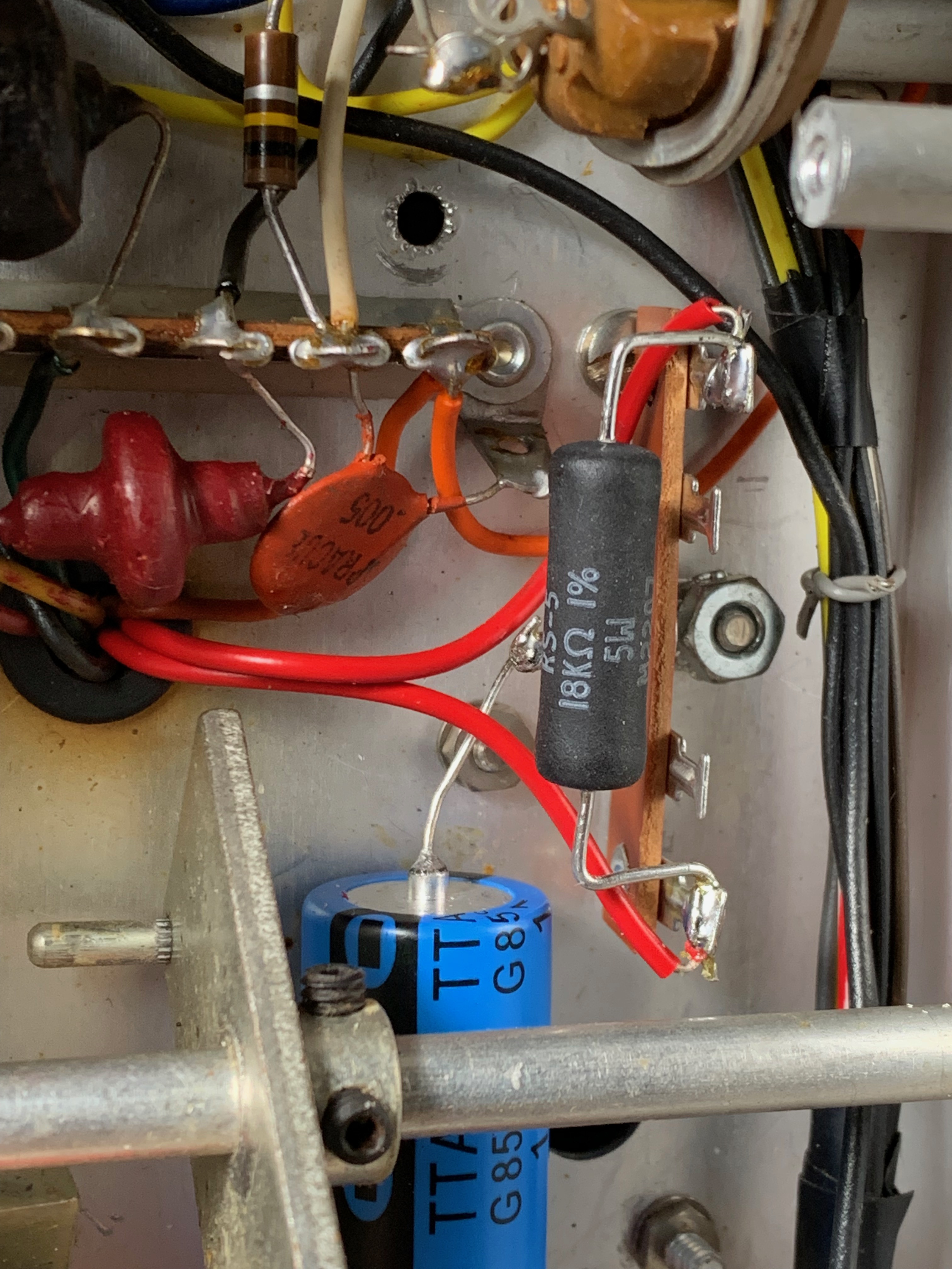
This was one congested place!  You can see the earlier mentioned two wires that were removed from SW4 (front) clip 8, soldered together, and the single black wire soldered to this pair, leading to the upper deck, eventually connecting to the pre-soldered K2 relay's black wire.  You can see the heat shrink insulation to the left, before I wrote "black" on it, and slid it over this junction and shrank it.  But you can barely barely even see SW4 (front)'s clip 6!  Soldering here could hardly be considered.  Not with my 20 watt soldering pencil.  I made a close inspection of the switch, both above and below deck.  No hobbyist with average soldering equipment is going to safely solder a connection to this clip as it is.  I was faced with a major task of removing, some how, some of this congestion and then re-soldering all of it.  That was not in the cards, gang.
 
With a flashlight, and with moving some of the wires a bit, I could find the green and white wire that was soldered to the clip 6.  According to both the pictorial and schematic provided by D-lab, this green and white wire ran directly to pin 3 of the 6146.  I looked at the schematic to see if there were other points along the way, or any terminus connections I needed to be concerned about.


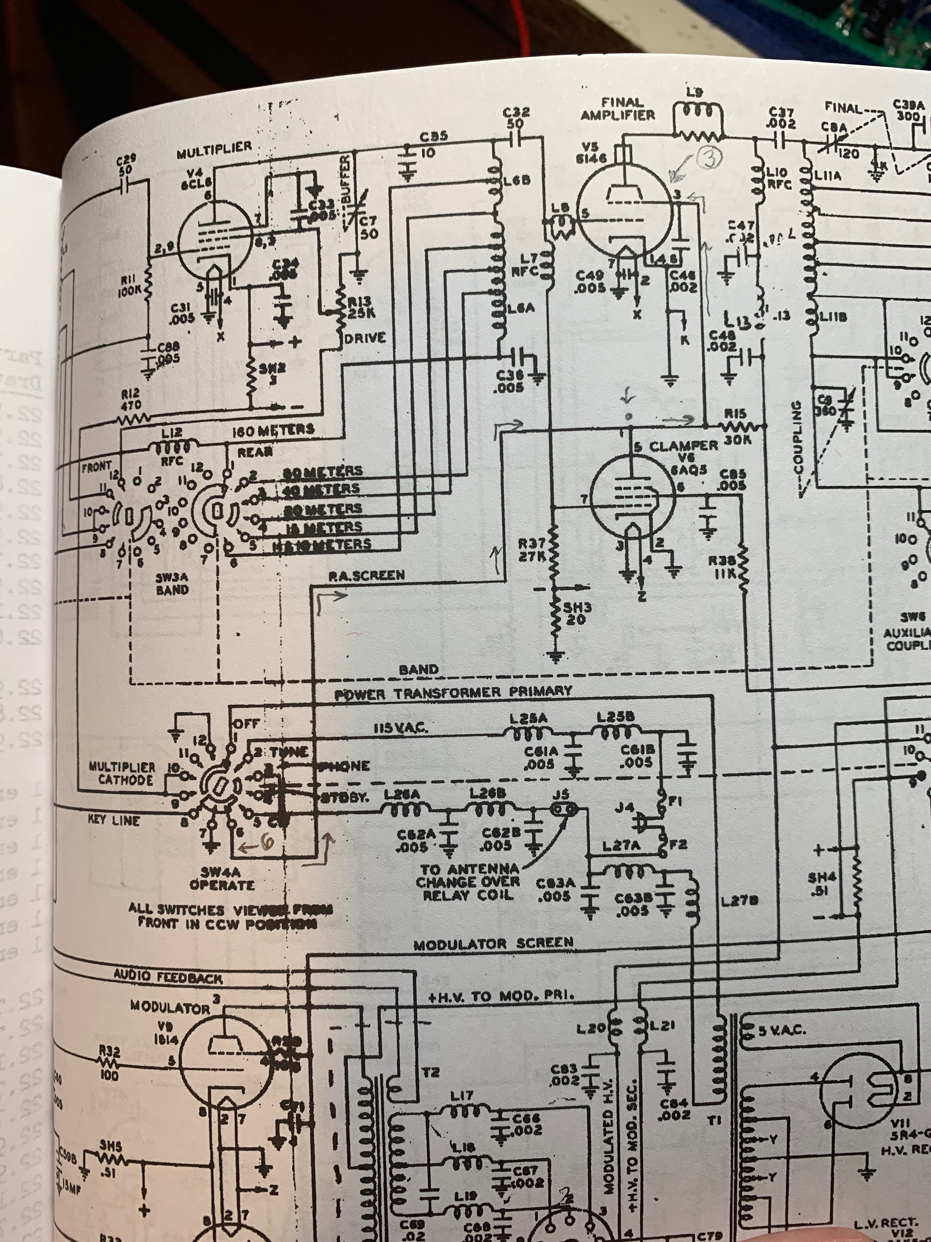
The schematic shows that green/white wire carrying the screen voltage to the 6146's pin 3, also to the clamp tube (6AQ5)'s pin 5.  Any where you tap along this line, the same voltage is seen.  RF is bypassed.  And while there is plainly printed on D-Lab's instructions to NOT solder the relay directly to pin 3 of the 6146, I could find no real reason why!  Another alternative would be to fish that green/white wire out of it's harness... which carried a gazillion other wires, and tap it... yet another mess.  Frankly, there was no good solution.  Soldering directly to clip 6 was clearly a disaster in the making.  On the video Terry said "it's do-able".  It may be on his early model Ranger, which has no key circuit sub-chassis, but in mine it would have been a mess.
 
So.... yeah, sorry.  I ran a wire down to pin 3.  
 
Shoot me, D-Lab.  I'm a scofflaw.  
 
But in retrospect, I still see no reason why not to, and to date I have had no issues in operation.


Maybe it's because I'm a home-brewer.... I'm used to things like this, tapping a rail somewhere along a  bus.  D-Lab never explains on the video or in print why tapping the 6146 screen-line is verboten.  I could just as well have tapped at that terminal strip to the left.  Or at the clamp tube.  Or at shunt resistor R16.  It made no measurable difference.  So use your own judgement, dear Reader.  And if down the line I do develop an issue associated with this, I will post and edit to this installment.  As it is, I am writing this installment well after the fact, after many QSOs using this Ranger, and the relay has performed flawlessly.  So has the Ranger itself.
 
'Nuff said.  
 
Meanwhile, above deck....


These are those pre-installed taped off wires I mentioned earlier.  Under deck they are connected where they need to be, and labeled as to which relay wire colour they attend to.  The key circuit deck was removed just prior for the wiring and the threading of these wires back up to the upper deck.  It is subsequently re-installed.


I mentioned these wires as being labeled.  Here is how I did the labeling: all the wires were pulled below deck at one point, with heat shrink slid over all squegg splices.  The associated wire colour is written on the heat shrink tubing itself.  After shrinking, these wires are fed back above deck as I just described, and wired to a terminal board which I mounted on the key circuit sub-chassis deck utilizing pre-drilled holes which happened to be a perfect match for one of my milsurp terminal boards.  Almost as if it that very teminal strip was meant to be there.  


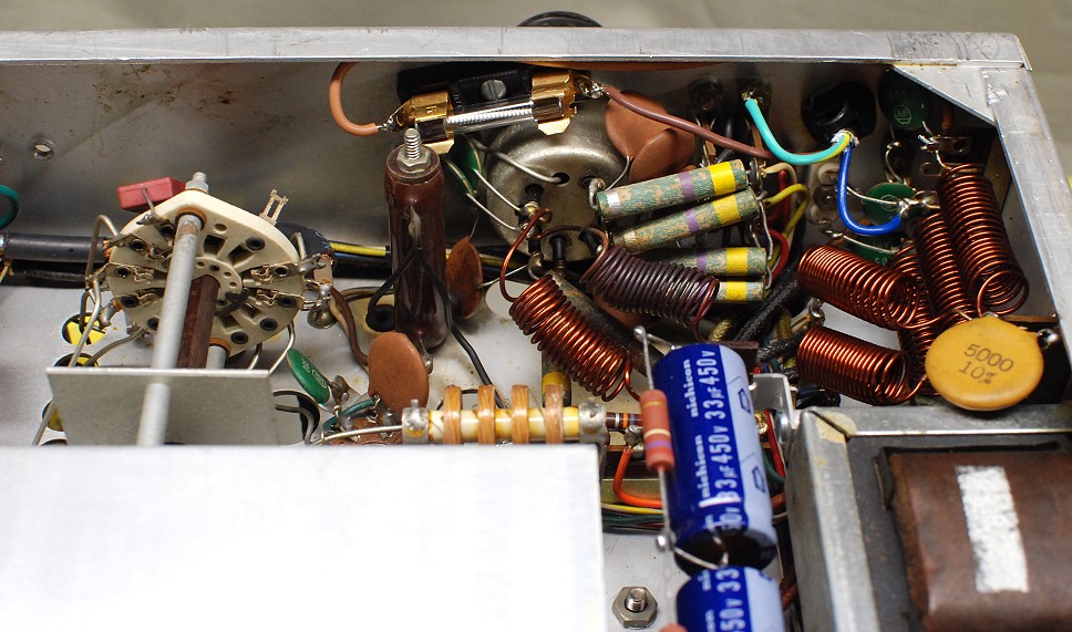
It all went together nicely.  Everything connected in an organized manner.  You can see the K2 relay installed, and the terminal strip that I mounted using pre-existing holes.  After this, the relay was tested for function without the 5R4 installed.  Afterward the 5R4 was plugged in.
 
Let me mention at the point the accessory plug, which I had to secure and wire up.
 
When I bought this Ranger, it had no accessory socket.  When I made the need known. one of the members of the Amplitude Modulation Classics FB group spotted me the male Amphenal plug.  I ordered the shell cover for it from eBay, and at the same time I ordered the two-pin Amphenol mic plug, also from eBay.
 
The wiring of this plug is simple, and I will post the wiring diagram, per manual schematic, also a couple shots of the finished accessory plug :


With the K2 Relay finished and tested, it was time to button everything up, slide the cover onto the Ranger, bolt her together, and run her into a dummy load and check things out.  But there remained yet one more thing to put together...


The D-104 mic.  This was as simple as 1-2-3.  Black and shield grounds to the plug shell (I tucked it under the spring which runs under the plug's collar, a good firm connect.  Audio goes to pin 1, and the mic's key runs to pin 2.  With that complete and installed, I gave her the "Smoke Test".    She passed with flying colours.
 
And she's still flying.
 
In summary, let me add that I did do one audio mod, which was recommended by Charles Rauch W8JI, and linked at Greg Latta's site.  Here, Charles writes:

Change  C-52 from 500 pfd to .02 mFd
OK, this is about the only major worthwhile effect, since it will bring low frequencies up several dB. In my own rigs, I've found that a change from 500 pF to .01 uFd was far more than enough.
 
Having changed out C52 between the first and second audio amps in the speech amplifier, I have received audio reports that range from "very nice" to "smooth" to "great!".  I'll leave it there, gang.
 
That's all for now.
 
de wd4nka


Gary's Awesome Adventures in Amplitude Modulation (AM Radio Transmission & Reception) :

Prepping the Johnson Viking Ranger for Station Use, Part 3. 


I took the liberty of posting Greg Latta's photo of the line plug and fuse mod, because, frankly, his photo was better than mine, and also there's not really that much involved.  


The fuse holder is ordered from Mouser as indicated on Greg's parts list.  I also ordered the three conductor cord while I was at it.  Simply follow the original cord connects, and wire the cord's ground to...well... ground!  You can also get a partial view of the HV filter caps and equalizing resistors.  Again, I did the very same thing.  I could find no better arrangement.


I found I had a little variance in the positioning of my particular fuse holder.  I don't know if Mouser started stocking a slightly smaller base holder or not, but I was able to place mine a tad more vertically with plenty of clearance and accessibility.  Apart from this, again, I followed Greg's suggestions entirely.

Having done the re-cap, next I took on: the much feared Chernobyl Resistor!  That famed 18K resistor, also known as "R3", that strikes fear in the psyche of all Ranger owners.  If resistors could talk, this one would sound like Boris Badenov!!  


 In all fairness, it's rep is well to pay heed to.  The collapse of R3 can cause damage to the VFO, and you don't want that.  Nosir-eee.

For this, I needed to remove the keying circuit sub chassis and remove all the tubes in the area including the two rectifier tubes to have room for the screwdriver.  Any terminal strip screwed onto the plate which faces the key circuit sub chassis should be removed as well.  After removing the cover plate, what you will see is what the above photo shows.  Boris Badenov's hide-out.  There he is, sneaky little devil, in the lower right.  Don't be fooled by the brown-grey-orange tricolour, its really the colors of Pottslyvania.  Fearless Leader probably has a cam hidden in there somewhere.  Probably as stash of Molotovs as well.  Proceed with caution.


Here's a closer look.  As someone on one of the Facebook Groups pointed out, it looks brand new!  It probably would have been years before it actually broke down.  But discretion (and and ounce of prevention!) is the better part of valor, says I, and I chose to replace it with a 5-watt wire-wound.  Also from Mouser.


I opted to install the replacement resistor under the deck but near to the VFO entry port, because while I wanted the heat to be conducted away from the VFO (there is some varying points of view on this), I am not really comfortable with long wire lengths being strewn hither and yon.  So, borrowing a convenient screw already there to ground one of the new electrolytics, I installed a new terminal strip on which to place the new resistor.


And there it is.  Looks good, easy to access, in an un-cluttered space.  Should I have used an 8 or 10 watter instead?  Maybe... but it's better than the 2-watt resistor that was there.
 
So, what's the story behind this critter?  Let's look at the math.  (this is a cut and paste from one of the forums dealing with the subject.  It was just easier to do this than to have you think I actually  sit down with the schematic and do this stuff.  I do, when it comes to homebrewing or reverse engineering unknown mods.... but this fella already had it laid out.  Colour me lazy.)

The (in)famous "Chernobyl resistor" (R3) is used to drop the 300 volt line to 150 volts. So there is 150 volts across it.

From this we can determine the current flow:

I = E/R

E= 150 volts

R = 18,000 ohms

I = .00833 amp or 8.33 mA.

This is reasonable because the 0A2 has a minimum current of 5 mA and the oscillator tube screen draws only an mA or two.

Now for the power dissipation:

P = E I

150 volts times .00833 amp = 1.25 watts

So a 2 watter is theoretically big enough.
 
...ahh, but over the years, guess what begins to alter value with heat?  Yeah, that 18k/2 watt won't stay 18k forever. and 67 years is a long time to dissipate.  Ohms lost means increased current and increased heat.
 
Yeah, replace that.   Whether in the VFO or outside, choose your poison.  The point is to protect your historic gem, there.
 
That's it for now.  More to come, including the installation of D-Lab's K2 PTT/ SS rectifier.
 
de wd4nka


Gary's Awesome Adventures in Amplitude Modulation (AM Radio Transmission & Reception) :

Prepping the Johnson Viking Ranger for Station Use, Part 2.

 
This is what I was facing.  Notice that the electrolytics are bolted to the chassis with a screw and nut.  Some of these screws are also holding down components above deck as well as below deck.  This requires a significant amount of accessing and removing screws from top mounted components.  Especially the modulation transformer, which required the removal of the meter shell in order to access that screw.  I will show you how I did this on the next installment.  In this installment I will show the below-deck work.
 
Before I go further, let me again refer you to Greg Latta's website resource.  On his site he provides a convenient list of components needed for basic replacement, and also where to buy them, mostly from Mouser Electronics.  His list has live links to further save you a lot of time and effort!  I will add that in the eventuality Mouser may be out of certain components, I also found Antique Electronics Supply to pretty much carry what Mouser does not.


I wanted to show this photo simply to illustrate just how fresh some of these parts actually were in my particular Ranger.  There are two pillars, or stand-offs on either side of that filter cap that will be used to mount the two series replacement caps and equalizing resistors.


I use a method of re-capping that is pretty controversial, it turns out.  Years ago I knew a TV repairman who would let me access his shop up in Casselberry (Florida) for used tubes and parts.  In the process he showed me his technique employed in replacing parts, especially hard to get to reaches where the soldering pencil may disrupt otherwise good factory solder points, or possibly melt the insulation on adjoining wires.  It was called "squegging", and involved the use of "squeggs" (sometimes called "squiggs" or "pigtails".  Mr. Collins, the TV repairman who owned the shop I mentioned actually had a box full of different sized squeggs, but I found I could replicate them easily with tinned bus wire.)
 
The technique involved using the original soldering joint if it was good and solid.  Most factory solder points are, especially in this era where factory solders were still made by hand.  The wire from that point was cut at the appropriate length, stripped at the end to expose the wiring, tinned, and the squegg was placed over it.  Enough room is allowed so the component to which you are solding to it will have enough room for its lead to slide next to it inside the squegg.  I go the extra length to slide a piece of heat shrink tubing over one or the other side of the connection.  Touch the pencil to the squegg just enough to flow the solder to secure the connection, then slide the heat shrink over the squegg and heat with your hot air gun on low.  I usually have a piece of angle aluminium to slide behind the connection so stray heat doesn't compromise the other components.  I've even used index cards for this purpose because the heat exposure is really minimal, and won't set your paper alight.  Aluminum foil can accomplish the same thing.


I use double round snipes, the sort florists use, to wind my squeggs.  Because of the conical shape of the jaws, I can actually create different diameter squeggs as required.  Other folks use a sewing machine needle or leather stitching needle held in a brace of some sort... I've used hand held drill handles for this... and simply wrap the wire around that needle.  Any way that works is good.


After the solder, slide the heat shrink over the connection and heat.  Note the angle aluminium piece that I use for heat shielding.  I have several different widths, depending on the situation.


Heat shrink tubing can also serve as a surface to label, as seen here when I wired in my K2 PTT from D-Lab.  When heated, the hand written labeling remained, so in the future I can pretty well tell where I am at.  I took this photo before I applied heat.  Here, the heat shrink is not yet slid over the squegg connections, all of which are in the clear, not under anything.


There are some connections where I did not need to insulate, such as grounds.  This photo was taken during the wiring of the HV filter caps.

 
I need not show every single detail in changing out the discreet components, every capacitor and such but I will touch on some issues I had to solve that were not readily apparent to me at the onset, most noteably, the removal of other parts to reach areas that, in turn, had to be removed.  These were the cases where the capacitor was held by a bracket secured to a transformer bolt which could not be safely removed from the bottom, but required access from the other side of the chassis.  These were the Low Voltage filter choke and the Modulation Transformer.


Referring to the top photo you can see the LV choke at the top of the inside chassis view, covering all beneath.  To get at these components required the removal of this transformer.  Even though the screws were readily accessed from the side apron, I discovered I still had to go inside with a short screw driver because the screw itself was pinned under the transformer yoke.  So I positioned a smallish screwdriver from the inside, and used a ratchet for the outside.  The other screw was not pinned, and so was easier to remove.


Here is a shot of that pesky screw.  Bolting back in was easy, especially since there was no longer a huge capacitor taking up all the space.


This cap required access to the screw that held down the Modulation Transformer.  Therein lies a tale.  That screw access was wholly covered by the meter shell housing.


This was the screw I needed to access.  No way to get to it.  In fact to get this close-up I had to use telephoto.  The on-line references that I could find dealing with the meter shield housing showed a different type, one that was more squarish with rounded corners.  This one is larger and seems to be more prominent.  It is meant to shield the meter from RF, and is a marvel of engineering, but taking it off was a bit of a process.


The meter shield is actually bolted to the meter connections themselves, which requires a bit of care.  There is circuitry that has to be removed, and the pilot light socket has to be pulled out.


 There is a terminal strip attached to the shell housing, connecting the bulb wiring, associated rf chokes and caps to the outside wiring.  These are removed.


Here is another view of the rf shell housing for the meter.  I believe the screws holding down the terminal strip are sheet metal screws, no nuts to fall off inside, as I recall.  In fact, in retrospect, it may not have to be removed at all.  Your mileage may vary on this.  I removed it because I didn't know how much room might be required to actually pull off the shell.  So I thought best to take everything off just in case.


Here is a clearer shot of the two screws and what is connected to them.  It's actually not a hard job to remove these components, just time consuming.  But don't be in a rush.  Use your phone to take photos as you go.  In fact, this was how I got all these photos.  Let technology work for you!  Photo as you go.


At this point it might be good to look at the screw mounting structure itself.  Here we have two insulated washers, a nut, the eyelet for the solder connections, a metal washer, and a nut.  Remember this order.  And those two fiber washers fit into each other, so don't mix them up.  As you remove them, note their order in place.  This will save you a lot of time in re-assembly.  Once you remove the upper nut and washer, lift off the eyelets, then un-tighten the bolt beneath.  Be careful, the screws are the meter's own connections.  Go gently here.  Remove the tightening nut, then the washers, keeping them together.  Then slip off the shell itself.


Here is what you will have "dangling".  Note that the meter circuit is connected to a terminal strip screwed to the VFO covering.


Here is the exposed back of the meter.  Notice the four small nuts surrounding the meter.  These are removed carefully to remove the meter.  This was necessary to get to the modulation transformer screw.  Needless to say, this was a project in itself.


I used tweezers to replace the nuts and to get them started.  They are small and it's a little tricky to reach them all.  They should not be very tight, just snug.  Once I got to the modulation transformer beneath, and removed the bolt and the cap it held below deck, everything was re-assembled in reverse order.  This is why I strongly recommend to take shots as you go, for your own reference.  

Next installment: replacing the power cord and installing an inboard fuse.

de wd4nka