All Things Wireless & Letterpress

All Things Wireless & Letterpress

Monday, April 13, 2020

Gary's Awesome Adventures in Amplitude Modulation (AM Radio Transmission & Reception) Part 2.


Actually, I was doing pretty well on 75m AM (3885 kc, of course!)  with 25-30 watts and my vertical.  I had spent half the year coming up with the best antenna arrangement I could produce in the space I had, and under the conditions I needed to work within.  I had tried dipoles of all sorts of configurations, random wires, inverted 'L's, loops, all of which did work, but the one antenna that consistently had me returning was my 40m quarter wave, which by now sported about seven 70-foot radials, along with the original ten 35-foot radials.  What really did the trick for 75m operation was inserting a matching coil in series with the feed, which over time I made switchable with a DTDP switch mounted in a weatherproof box.  It switches the coil in and out of the feed line.  I still have to go outside to flip it, but it is better than having to unscrew, unbolt, then re-screw the feed to it's feed points.  Much less wear and tear on the feed point and the transmission line!
.

.

It's a simple little coil wrapped around schedule-40 pvc (around 1.75" O.D.) using 12g insulated solid core house wiring.  I kept the coaxial RF choke in line, which keeps me out of the TV cabling nearby when running the amp.
.
Another thing I added but didn't think to photograph was my new ground system.  I drove several 8 ft copper grounding rods along the side of my house separated by about ten feet, all wired together with heavy copper wire, which grounds my antenna and my station.  It may make thing run a little quieter, hard to tell with the bands already noisy from the atmospherics that happens down here in the deep south surrounded on either side by two major bodies of water, the Gulf and the Atlantic.  But it does provide a bit of added safety. 


Here  are two shots of my antenna, one with the choke visible.  You can get an idea of how high the feed is above the ground....about two ten-foot mast sections high, bolted against the gable end of the house.  The switch and coil are out of sight, but are positioned to the left of the base, some distance so as not to muck with the coil inductance.  The antenna is 33 feet high, and a few of the seventeen radials can be seen spreading out from the grounding plate.
.
Added to this is a little bit more power behind the carrier, courtesy KA4USN, Ron up in McClenny, FL.  It's a Collins 30L1 linear amplifier (shown above in the top photo), sporting four 811As.  I like the 811A because, well, I have had a background with them from my Johnson Courier days.  They must be tuned a bit differently for AM as opposed to CW or SSB, and for any CDC service such as RTTY, carefully so.  The best advice I've found so far on how to tune these sorts of amps.... designed for ssb.... comes from Owen Duffy, which advocates - based on their computer modeling of the 811A - tuning the amp within a range that protects the plate (Anode) of the tubes, which have a plate dissipation rating of only 65 watts per tube.  You can find this information here.  It involves driving the tubes at minimum drive, maximizing the tuning of the amp for highest output, and then adjusting the drive alone to achieve about 120 watts, which keeps the finals well under their max dissipation level, but will provide about 490 watts at voice peaks.  The conventional method of tuning "for full smoke" will provide greater power....but at power levels significantly above the plate dissipation level.   And AMers do like to put a brick on the mic!!
.
You might note the thermometer on top of the amp in the photo at the top.  It is a digital thermometer sensing the air flow from the muffin fan set atop the amp to monitor the heat.  At this point the max temp with a one minute key down at max power is 110 F.  It normally runs between 95 and 100 F.  That is fairly cool for four clustered valves like the 811A.  Of course this muffin fan is in addition to the fan already part of the amp itself.  It's got great airflow.
.
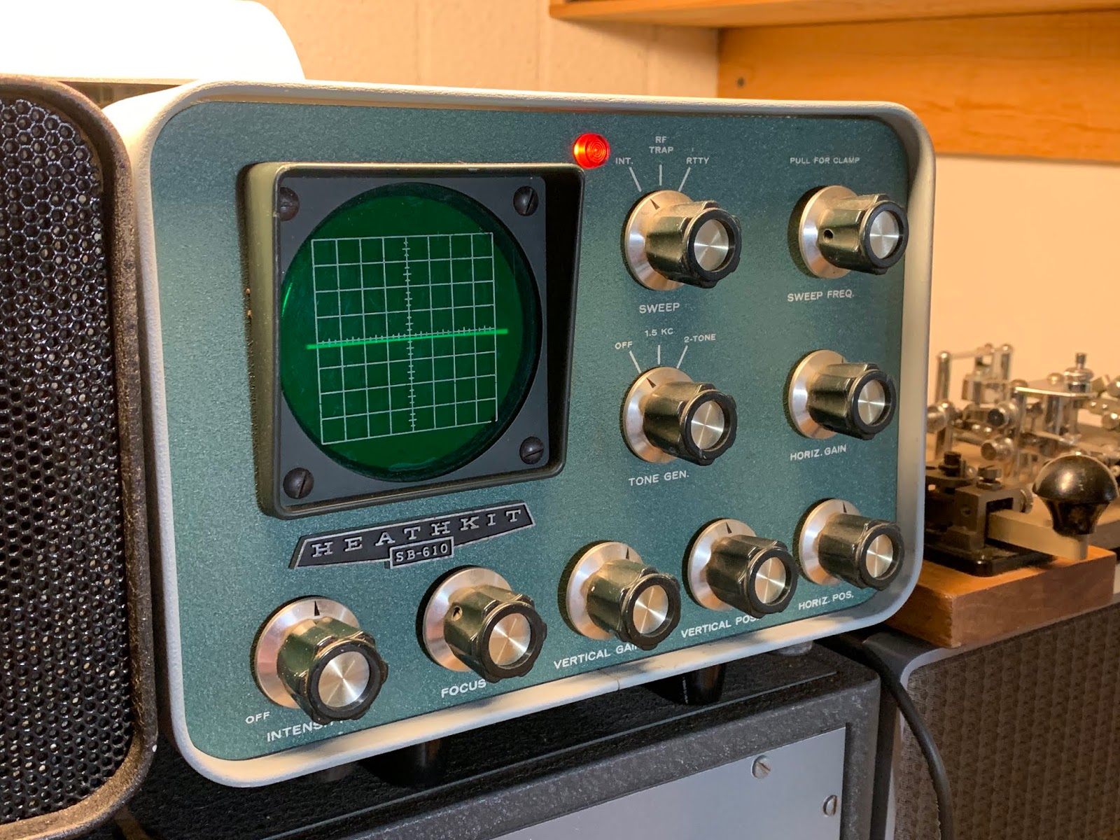
One more addition I will include in this installment: my new-ish Heathkit SB-610 Station Monitor, which I purchased at this year's Orlando Hamcation.  This provides me with a needed reference for my modulation, which up to now I relied entirely on reports from other stations, metering, and my own audio monitoring through the receivers.
.

.
This Oscilloscope was designed for the SB series Heathkit transceivers and provides a fair assessment of modulation integrity.  Not perfectly but effectively.  I had to read up on how to use it, and between my 1954 ARRL Handbook and the manual that came with the unit, I could actually catch a visual of my modulation envelope.  
.
While the monitor does come with it's own one and two tone generators, they are a bit weak.  That is something I will work on later.  So I set my modulation from a live digital tone generator and a live mic.  Switching the FT-101EX over to a dummy load, I sent a 400, 900, and 1500 cycle tone to the mic and watched as my envelopes displayed a heavy overmod pattern.  Note that I am not using the trapezoid pattern: that requires a bit of re-rigging of the scope inputs, but I will eventually do that re-wire and take a look.  But right now I was able to get a feel for the signal at different levels of audio frequencies and speech amp settings.
.
I check the monitor both with the exciter alone (FT-101EX) and with the amp in line.  The amp does provide a very faithful reproduction, which showed that I only needed a bit of tweaking of the audio with the amp on.  Barely a touch.
.
.
Here we see a bit of over-modulation using a 900 Hz tone into the dummy load, the tops of the envelopes are flattening out using a 900 cycle tone, and there is a gap between the envelopes.  


With a bit of reduction in the mic and speech amp, I was able to maintain a good average looking envelope at all the different audio inputs.  I learnt that if you keep your eye on the middle, the zero voltage point between the envelopes while speaking into the mic, you can  kinda gauge the thick or thin nuances of the center line as to whether you are tending heavy or not.  When speech is monitored, of course you get a whole jumble of wave forms, not this pretty train of envelopes as you do with a single and steady tone.  But if that center line looks pretty thick as you speak, you can back down on the audio and watch it thin out very noticeably, keeping an eye on the peaks to avoid flattening out.  When I say "thick", I don't mean wide or broad, as in an undermodulated carrier.  When you overmodulate, the waveform gaps between the envelopes but the oscilloscope still shows the zero voltage  line.  When you speak, the various wave forms created by the speech will all have that gap and zero-line between them.  That gap becomes noticeable as you talk because the zero voltage line actually starts to emphasise itself (on my scope it actually gets more intense).  When you reduce the modulation that zero-line will become less bright, or intense.  It's turned out to be a good "on the fly" adjustment technique.   The reports from others, plus a monitoring of my own voice over the 'phones pretty well confirms this.
 .


Just to compare, here is an under-modulated sample of that 900 Hz tone.  Note the amplitude is lower, and the center line is thicker.   Probably a better way to monitor the signal in action is to set up the scope for a trapezoid patter, but that will be down the road apiece, as this requires a special x/y axis hook-up, which can be done.... the manual explains how to do it. 

All in good time.
.
.
So, here is where WD4NKA is at now.  That speaker on the amp is not there, now, it was just a convenient place to park it at the time of the taking of this photo.  It's a not-too-easy-to-find Hallicrafters speaker, which sort of reminds me of a drive-in movie theater speaker, lol!  The D-104 in the foreground is an amplified version, probably dating to the 1980s.  I used the Station Monitor to set it as well.  It's barely amplifying, but it does make a difference in how the station sounds!  It tends to add a bit of low frequency to a normally higher pitched mic.
.
These days I find myself switching between 75m (3885 kc) and 40m (7287 kc) as the mood strikes.  My operating time is normally between 5 am and 6 am EDT on either band.  Forty meters is quite nice at this time of the morning, being the dawn-side of 'grey-line'.  There is rarely anybody there.  I find myself using three webSDRs to get a feel for where the band is going, KFS on the California Coast, K3FEF in the Pocono Mountains of SE PA, and VE1BWI in New Brunswick Canada, on the North East PEI area.   When I call cq on 7287 kc (I use this odd frequency so I am not mistaken for a Broadcaster on, say, 7290 or 7285 kc), at some point I will indicate which webSDR hears me best, as a courtesy. 
.
So that's the AM station, gang!  And as i said in the last installment, WD4NKA-AM is a work in progress.


Monday, January 20, 2020

Care and Feeding of the 811A

From the get-go, let me first say I'm not a techy-kinda-guy.  I never thought I would publish my thoughts on this subject, but I feel compelled to, largely because what I read in text and published reports based upon modeling and practical application regarding this legacy triode is so, well.... opposite of what I actually hear about how folks operate these tubes in real life.
.
The 811A is really the only valve I ever ran as a linear amplifier, and having two Johnson Couriers in the course of my ham radio life, they seemed to me to be relatively bullet proof.  The Courier had a pair of 'em, and I drove them with my Hallicrafters HT-37, driving them at the tune of what was probably about 25 watts.  My watt meter read an output of over 100 carrier watts, and if I figure things correctly, I probably realized just shy of 400 watts pep.  That amp ran cool, and those tubes were old when I got either one of those Couriers.  The only thing I ever did was either solid-state the power supply in one, or simply rebuild the other, replacing the 866 rectifiers with some other recommended tube that glowed orange, a 25-something or other, I forget.... but it handled the 1700 volts DC just fine.
.
Ok, fast forward about two decades, and I find myself once again with an amp, only this time I have a cluster, or "quad" of four 811As.   And I begin refreshing myself back up on how these amps tune, what to expect, etc., how the relay connects (it's a Collins 30L-1), and most importantly, how my amp really wasn't meant for continuous duty cycle modes (cdc modes).    Since my primary intent was just that, AM, pretty much the ultimate in "CDC"modes, my investigations went another direction.  I did a lot of reading and a lot of asking around, and the reading began to depart in results and findings from the on-air asking.
.
On the air, I got advice something like this: "I always do max drive and max out.  I always tune to "full smoke", and then, back my drive down to permit a good amount of 'head room' "
.
So, what this means is max input, max output (maximum amplification efficiency), reduce the drive.  Ok, makes sense.  Sounds good. In fact, that's what I always did myself.  My max input drive to those two Courier 811A's used to be about 20 watts max.
.
But that's not what the on-air guys were talking about.  They were talking about much higher maximum drive which could be northward of 70 watts carrier, 280 watts pep!   Max that, then pull the drive back, without re-tuning the tank.
.
Now, that last piece was something different for me.  I never in my life ever altered the input of a final tube without touching up the output, because any change in input alters the load the tube faces, it changes the characteristic impedance, the tube is operating under a slightly different metric.  In most finals, you always "touch up" the finals, last thing.
.
But, I get it.  We are talking about a modulated wave that is varying by 3-8 kc, not a cw signal where we only had to worry about one frequency, which never changed.  In AM, the amp has to handle a range of frequencies varying at an audio frequency rate, as high as 16kc side to side of carrier.
.
But I began to also pick up comments of another sort.  Folks who "used to run" amps with 811A's, and after a time, sold them and went to 4-400, 3-500z or at least a couple 572's.  They had common complaints as I indexed them in my mind: "they ran really hot", "I had to replace them after a year", "I had to keep my transmissions short". 
.
I never had that issue with my Couriers.  I could lay a brick on the key, that amp would stay cool, and it had no fan.  Just a lot of ambient air circulation.
. 
Now, my reading took another direction, as I mentioned.  While some material did seem to indicate the common tuning consensus, other material reminded me of this thing called "Maximum Anode Dissipation".  Wow.  I haven't dealt with plate dissipation in years, since my General Exam, actually.  The MPD (or MAD) is simply the maximum power which the plate of any tube can safely dissipate.  In the case of the 811A, that would be about 65 watts.
.
Now, in my past rigs, all built for cw, we routinely went beyond those ratings because of the nature of morse code.  The tube isn't "on" long enough to heat up, so we would drive those finals well beyond their MPD ratings.  In the case of the "R-7" mopa rig described in the 1947 E&E handbook, we could drive the 811A to a grand output of 100 watts, with over 140 watts plate input.  That's a full 75 watts beyond it's ability to safely dissipate the heat off it's plate!! ....but again, morse code is a rapid, on-off keying.   So "max smoke" is maybe ok for this mode.
.
Single Sideband, where there is no carrier, only the stored power of the sidebands presents a similar load to any power final.  Only more rapidly so, but there is no continuous carrier to deal with as long as the mic is keyed.  Again, this permits the final to go beyond it's CDC plate dissipation rating.  Actually, well beyond it.  And tuning for "max smoke" can work here too.
.
The picture is this: you can get a lot more power out of any tube than its plate can safely handle over time.  Just as we could get 100 watts out of a single 811A driving the snot out of it, if we put a brick on that key, that tube would last about 5 minutes.... maybe.  That plate would give off a very nice cherry red, then go to white, then "boom boom, out goes the lights."
.
Anyone who has built and operated an original QSL-40 knows the principle, here.  It's call "pushing".
.
Computer models show that as the resistance facing the 811A increases, and as the drive power decreases, it's ability to handle power at the plate also increasesAs this resistance  lowers, and drive increases, ohms law takes place, more current flows, P=IxE happens, and the power which the plate has to handle exponentially increases. Even though more power is expressed at the output, the actual amplification factor decreases. This means that even though you may be getting the power you want out of the final, that plate is working overtime to achieve it.  It's heating up really fast.  There are some diminishing returns happening.
.
The handbook tells me that efficient operation of a valve mathematically drives it well beyond that MPD, sometimes to the tune of 10x.  It also says that as this "efficiency" increases, the amplification factor begins to decrease after a point on the curve and increasingly non-linearly so.  As such, we need to define what we mean by efficiency.  
.
Efficient electrical operation - power output - or efficient safe plate dissipation with somewhat less electrical efficiency. 
.
When you set your drive to max, 70 watts and higher, the output tank is adjusted to dip, or  resonance at a relatively lower Z, lower resistance at maximum output.  This actually increases the power transfer efficiency of the tube!  The model shows that the plate (anode) is being forced to dissipate over twice it's rating.  At this setting, if one tunes to "max smoke" and simply cuts back the drive without changing the Z of that pi output tank, keeping the plate facing that very same impedance, the drive would have to be lowered such that the maximum output of a quad of 811A's would be reduced to about 100 watts, or as Owen Duffy indicates, 70 watts to put those plates in the safe range.  The remaining 260 watts is being dissipated as heat from the plates.  That's 70 watts of amplifier output.  That's what it would take to operate that amp with a brick on the key, and keep those plates happy and safely below it's MPD rating if tuning with max drive for max output, and leaving the output tank tuned right where it is when cutting back the drive.  This is probably why I hear the overheating and shorter valve longevity stories.
.
AMers tend to hold that key for almost broadcast-length times.  One fella up in Indiana I actually clocked at about fourteen minutes on a single transmission.  My hat is off to his 3-500Zs.  Maximum plate dissipation, thy name is Amplitude Modulation! 
.
Now, I have also heard of a lot of ops replacing their 811A's with 572B's, a direct replacement.  Now, we have a valve that has a MPD of 165 watts, rather than only 65 watts per tube.  Whole different story.  And the "Max Smoke" method probably gets by ok.  But that's 2.5 times the MPD of the 811A.  What does that tell ya?
.
Computer modelling shows that when the 811A is driven by minimum drive, then the pi output tank is adjusted to a higher Z, a substantially higher resistance, and the plate can handle higher output power before that plate starts heating up into the danger zone.  The suggested drive was about 7-10 watts!  This falls in line with what I read earlier about the relationship of the output impedance to the input drive. 
.
So, this was why many of these amps, such as the 30L-1 have actually told their owners in print to stick with SSB or CW, and that their amps were not built for AM or RTTY.  And indeed, using the "full smoke" method, they are not.  
.
But it doesn't mean they cannot
.
This morning I talked to a fella who told me about his Ameritron 811 amp he used to have, how hot it got, and how he had to keep his transmissions short.  He eventually sold it and got his (probably current) amp, I think it's a Heath SB220.  Good for him.  He can safely tune to "full smoke" with all the headroom in the world to PEP that 1600 watts!
.
As he was talking, I noticed my own amp.... four 811A's.... which I have installed two thermometers, one digital - sensing both the ambient air and the evacuated air.... idling at 75 degrees Fahrenheit.   When it was my turn in the round table, I keyed down for about two minutes, maybe three.  My max temp at any time this morning was 85f.    The ambient temp in the shack was 72f.   When my shack temp goes up to 80f as it can do in the afternoon, that amp maxes at 95f after about a two to three minute key down.
.
I attribute that to tuning according to what the plate dissipation will handle.  Taking the advice of the data supplied, I drive the amp with about 10 watts from my FT-101EX.  I tune to a dip at 225 mA.  I am realizing 125 watts carrier, about the same if I used the "full smoke" method, and have equal head-room.   Apart from a slight hum (I need to eventually replace the filter caps in the Collins) my signal sounds great from all reports.  One fella even scoped me at his receive.  Alles ist in Ordnung.
.
This might also explain why I had such a good experience with my Couriers, and why they ran rather cool without forced air.  Tuned to max with minimum drive.  My old HT-37 could produce maybe 20 watts of carrier. 
.
Likewise, the chief thing that I notice is how cool this amp runs compared to the on-air descriptions that I have heard over the past half year of asking around and simply picking up conversation on the subject.
.
This all made sense to me and reminded me of my earlier years building cw rigs, mindful that I could get away with "full smoke" with my Class C cw amps because heck, I was doing 20 wpm!  They wouldn't stay keyed long enough to heat up.  But oh yes, during tune-up, I saw many a plate glow with fierce cherry-red ness unless I unkeyed.  I was reminded that I was skating by with my over-drive.
.
So, am I over obsessive?  Maybe.  But I am also on a budget.  I need these valves to last a long time, longer than the year or so I have heard so many describe as their replacement cycle.  I can't help but think that "max smoke" is the main culprit.
.
Another phenomena I find: when I do get into conversations regarding linear amplifier tuning and the 811A's, MPD is usually never mentioned or even considered.  When I describe all I have mentioned above in this post, I usually receive an annoyed tone, being told that I need to do maximum smoke, that that's all there is too it!!
.
Well, as one op from KY told me (the one who described how hot is Ameritron 811 got and how he had to replace the valves about once a year!): "well, Gary, you do what works for you.  And if you're happy, that's all that matters."
.
I agree.  But I also want my tubes to be happy as well.
.
Well.... a year from now we'll see how things go.  BTW, KA4USN, who was the prior owner of this 30L-1 indicates the valves to be several years old.  Not ancient, but not new.  Ron is an old CW op who used to build his own equipment, we got our licenses together.  Methinks he also tunes with MPD in mind.   Just my suspicion.
.
73, de wd4nka. 
.
Just as an addendum, here is probably the best published explanation on this topic, specific to the 811A triode:
.

Collins 30L-1 and AM
The Collins 30L-1 is a heritage linear RF amplifier using four 811A triodes.

The manual gives no guidance on the use of the 30L-1 on AM, and that leads some users to think that it isn’t suited. This article explores the 30L-1 using the model described at RF Power Amplifier Tube Performance Computer.


The 30L-1 is specified for 1000W peak DC input in SSB telephony. This imposes one constraint on its use for AM, the other constraint is anode dissipation.


Tuned / loaded for rated SSB telephony

If the PA is tuned and loaded for 1000W peak DC input in SSB telephony, one would expect an output of about 680W PEP.


The carrier power for normal 100% modulated DSB AM is 25% of the PEP, so the carrier power for 680W PEP is 160W. However, at this level, the anode dissipation would be 294W, in excess of the valve ICAS ratings of 260W for four.


If drive was reduce until carrier power (amplifier output) was just 70W, anode dissipation would be just under 260W, and PEP would reach 280W. This clearly does not exploit the 30L-1 very well.


Tuned / loaded for AM

Reloading the 30L-1 for a higher resonant load impedance at the anodes will allow operation at reduced power for AM (due to the dissipation constraint) at higher efficiency and within the dissipation limit.


The RF Power Amplifier Tube Performance Computer gives us a tool for exploring different operating conditions without risking damage to the valves.


If the PA is tuned / loaded for a little over 500W PEP (say 510W) with the least drive, the PI coupler is adjusted for the optimal resonant load for AM within the dissipation limit. AM drive is then adjusted for 122W carrier output, and modulation will take the signal to 488W PEP.


Output power is 74% higher than under the “Tuned / loaded for rated SSB telephony” heading above.


Under these conditions, anode current should be about 228mA DC, and assuming the DC input voltage is 1700V+30V drive, DC input power should be about 1730*0.228=394W, carrier out should be about 136W at the anodes, 122W at the output terminals, leaving anode dissipation at about 394-136=258W.


Summary

The above is a procedure to adjusting the 30-L1 for optimal AM telephony operation within the dissipation limits of four 811As. Under those conditions, it is capable of 490W PEP output, which is about 72% of the PEP capability in SSB telephony.


© Copyright: Owen Duffy 1995, 2019. All rights reserved.

Wednesday, January 1, 2020

Gary's Awesome Adventures in Amplitude Modulation (AM Radio Transmission & Reception)

This is what I call my "AM" position at Station WD4NKA.  I have a few positions at the control console.  I also have a "NRR" position, a medium power code position for "Novice Rig Round-up" events which is entirely Hallicrafters "Grey-Line" 1961 equipment, and the other is my Sideband position, essentially a Kenwood TS-120-s.   This installment, however, will focus on the on-going evolution of my AM position, which has posed a real challenge, and for several reasons:

1.  I live on a small residential lot.  Approx 75 feet by 50 feet.  This pretty well precludes full sized wire antenna types in the main.  At least, the half wave dipoles.

2.  I already have a full quarter wave vertical and radial field for my 40 meter work bolted to the gable end of the house.  At least I did until early summer 2019, when after years of service, a storm damaged it, and it had to come down.

3.  I have limited space and limited power supplied to my radio room, which is shared with my Letterpress Print Shop which also pulls it's share of current.

4.  I have a sand pile for a soil substrate.  I live on a sand pile, essentially.  Historically awful to nearly non-existent ground. (ergo the elevated 40m vertical!). Not good for RF grounding.

5.  I have a sweet wife that puts up with my various avocations without complaint, but who also really doesn't want the house to look like a bird trap for condors.  The neighbours would also like to maintain their property values.

6.  I live in "Hurricane Crossroads", which proved itself in 2004 when in three months three hurricanes criss crossed over my roof.  Yeah.  Whatever I put up has to come down, and sometimes with very little notice and no, I can't take off work if the down-time comes in the middle of the week.  So whatever goes up must come down inside of an hour.  Completely down and secured.

Add this to a huge interest in Amplitude Modulated wireless signal.  I guess I love the way a receiver behaves when it intercepts an AM signal and extracts what is often some very nice sounding audio.  It's a nostalgic sound.  It involves nostalgic equipment more often than not, although lately some very nice digial AM equipment has come to the foreground.  But as a former MWdxer and low signal buff in general, I love the challenge of AM low signal work.

Getting Set Up
I already knew that while my early AM exploits (I had a Hallicrafters HT-37, Johnson Courier amp and a National 303, later a 300 receiver about 20 years ago) took place on 7290kc, these days most of it seems centered around the 75 meter "AM Window", 3880-3890 kc, most specifically 3885 kc.  I had nothing on the roof that was actually designed for 75m.  Nonetheless I was up to the challenge, so, about two years ago I began my re-entry into AM by trading my HQ-170 for a "Red Letter" HQ-129-X, a truly awesome AM receiver, and not too shabby for cw, either.  These became my ears.  I kept my extra HQ-170 speaker, btw.

But what to transmit on?  My DX-40 was great for cw, but it's audio section needs rebuilding.  My HT-40 is a good prospect at 15 carrier watts, but wait.... what about my Yaesu FT-101EX?   I found I could get about 25-30 watts carrier safely from it's rated 120 watts PEP.  And, it would take my old HT-37's mic, my 30 year old amplified Astatic D-104 without modification.  The FT-101 and D-104 have since become inseparable.

The opening photo shows what I arrived at for apparatus.  Yes, I have to switch, manually, between the transmitter (FT-101EX) and the receiver.  But I grew up doing this as a Novice for my cw rigs, it's all old hat to me.  All of this was to play through my newly rebuilt 33-ft 40 meter quarter wave vertical, now sporting brand new aluminium tubing from DXengineers, and about ten 35 foot radials fanning across the roof.  It is a stunning performer on 40 meters!  But for 75 meters, it's only an eighth-wave length vertical!
.

This is the vertical, base fed through a coaxial RF choke.  The feed point elevation is approximately 20 feet from average terrain.  It is quite heavy, so  I have it bracketed to about five feet of extended mast for windage purposes.  It does not seem to have a coupling effect on the antenna at all.  The base of the antenna sets in a 5 foot section of Schedule 40 PVC.  Any coupling to the mast seems to be more than offset by the fairly large radial field.
.

This is a shot of that "radial field", which may look a bit confusing.  The red wires are the radials, the black lines are shadows.  The radials are elevated about two feet and taper downward to the roof level.  At the point this photo was taken, I had about ten radials fanning across the roof from WNW to ENE.  It works nightly into Italy at S9 to 10dB over on 7195, talking to Roberto in Cremona, but then.... he hears EVERYBODY at least S9 with his set up.  But, it makes me feel good, anyway.   Graci, R-r-r-r-roberto!

So, the first real challenge: how to put this antenna on 75 meters?  The most simple and obvious method was using what I had: my Dentron MT3000A tuner!
.

That tuner occupies the lower left section of my Hallicrafters 1961 Novice Rig Round-up position.  It's probably the most versatile and most used piece of equipment in my shack, and represents the high-point of Dentron Construction.
So, feeding the coax directly to the tuner and through it securing a match to the FT-101EX, and getting a decent power setting such that my modulation didn't suck back the output power too much, I then proceeded to enter the world of 75 meter AM phone

Being Heard
At first I tried calling stations in the evening.  I did manage to raise a few stations, and with mixed reviews over my signal strength which was predictably quite low and frequently victimized by QRM, QRN and QSB.   When I tried to check into a group of stations, I was rarely heard.  These stations were pounding each other with 20dB over S9 sigs, and probably their AGCs were not quite recovered between transmissions, so they really never had a chance to hear my S5 signal.  They were rather rapid with their modified PTT rigs, none of them having to flip switches to cross over transmitter to receiver like me.

You may ask why not just use the receiver in the FT-101?  Passband is uncomfortably narrow although I do use the receiver to zero in on a signal.  The AM filter and installation was about as expensive as my Hammarlund, and from reports I have heard, no where near as nice.  Ergo, the separate AM receiver.  I have to flip it to stand-by and switch the transmitter over to the antenna, so two switches are flipped for transmit, and again back to receive.  I like it.  That's how my CW operation has worked for 42 years, why stop now?

In time, I began instead to try early mornings around 5:30 pm, and check in with the 3885 morning AMers.  This proved better.  At least, some of them could hear me.  Most importantly, they did not communicate annoyance toward my low signal.  This alone pretty much kept me encouraged to continue to improve my station.  You can really shut a guy down from the start with negativity.  These guys were really encouraging to me.
.
Antenna Experiments and Adjustments
For the past half year or more, I also experimented with alternative antennas, all wire oriented.  Random wires, quarter wave length overhead wires, various types of dipoles, an attempt at an inverted L, all of which had to go into the trees in the extreme ends of my property where lengths could be the longest, or as in the photo, various "L" configurations.  This one was probably my best wire antenna, going out to the front yard tree some forty feet, then another fifty feet across the yard up at about 30 feet terminating into another clump of trees at the front corner of my property, a total of 80 feet, coax fed, with the braid grounded to a radial counterpoise.  It actually had some merit beyond all my other wire antennas that I could work within my limits with, but over all, the 33 foot vertical still out performed all my wire antennas, as was shown over time on the air switching back and forth over every conceivable operating environment/ band condx.  This was especially true after I installed four radial wires cut to 70 feet.  This seemed to make somewhat of an improvement on my 30-watt signal.  Using this vertical operated, WD4NKA operated mostly between 5:30 am and 6:30 am Eastern Standard time in the Summer, Fall and now Winter, with average results something like this:
Florida Panhandle: below S9, sometimes well below until sunrise, then sharply increases to an average S9- 10dB over. 
North Georgia/ Tennissee/ Kentucky:  I do these regions best, KK4GZQ often doing the role of personal relay for me.  Very often he and other KY and TN stations report me consistently with S9 or above.  Sometimes well below, but on the average, I can be heard well.
Carolinas: I do well there on the average, at least until sunrise.  Frequently well into the morning.
Virginia: Normally reports me as well above the noise, with the occasional QSB dip.  This is on average.  Some early mornings it's better, some far worse.  But on average, quite communicable.
Indiana, Illinois, Ohio, Wisconsin: These are about half and half.  Half the time my little 30 watt AM signal can be clearly heard, half the time poor Kevin, KK4GZQ has to relay.  So, it's a crap-shoot.  When it's good, I sound very good.  When not good, no copy or barely so.
Pennsylvania:  Pittsburgh and Philadelphia often times give me opposite reports.  I am heard on a better average there as opposed to Indiana, although sometimes I think it may be by web SDR, but when I am directly heard, generally I can be clearly understood, if not with a mounting respectable signal.  New Jersey tends this way as well.  Normally, if they cannot hear me well, I also cannot hear them well, and so it is up into New England.
New England States: is pretty iffy.... but generally they report me just as I might report back to them.  Rarely can I hear them well without they not at least copying me.  Generally, if I am at noise level, they are same on my end.  One memorable early morning, Tim, up in Maine, remarked that I should get an amp.  I had to chuckle: I could barely copy him.  In fact, I think Perry, W3MMR may have had to repeat what he said.  Maine, Connecticut, Mass, in general, have never really given me the signals I get from Kentucky or Virginia.  In fact, a PEI station actually came over louder a few times... go figure.
.
One thing Tim mentioned along with "get an amp",  was "...if he might try to throw a matching coil at the base of that thing and feed it at that point..."
.
Of Course!  The Old "Gotham Vertical" thing!  Thanks, Timtron! -and I immediately set forth experimenting with what coil dimensions I might need.
.
I already had a  2" diameter section of PVC wound with Nr. 14 gauge solid copper house wiring, with insulation removed along a strip of the coil permitting tapping.  I connected the center conductor of my coax to a clip, the braid to the radials.  Then I moved the tap, taking swr measures, up and down the ladder to the roof.
Having finally found a good match, I secured the tap and tried it out the next morning with the AMers on 3885 kc.  The results were remarkable!  Increased average signal, and more folks on average able to copy me.  It was frequently remarked by other stations over time what a difference adding that coil made.  So, I wound a permanent coil, installed it, and here we are:
.
For those curious of the dimensions, the coil form is sched. 40, 1-1/2" inside diameter, 1-7/8" outside diameter.  There are 14 winds of Nr. 14 solid copper house wiring.  This can be further tuned to an absolute flat 1.0:1 match by adjusting the telescopic tubing, but it was not necessary for me.  As you see it here, the match is 1.2:1, and pretty well maintains that match from 3700 - 4000 kc.  I do have the coax fed through the MT3000A, which has a "straight-through" position, and two other coaxial inputs, plus a balance input and one for a random wire.  I forgot to drill a "weep hole" at the base of the PVC into which the vertical base is seated, so when it rains, I think moisture collects and the swr goes up to 1.5:1, but I can drill a couple holes through the base end-cap.  I will be more than likely enclosing and bracing the coil soon, just to tidy things up and improve the appearance.
So, this is where I am now.  Still at 30 watts mean carrier with about 120 watts PEP.  Still using the FT-101EX and D-104 mic, which I am dis-inclined to cease using.  Here's why:
This microphone focuses the bulk of its energies in the audio mid-ranges.  Mid to higher frequencies, really.  It is a communications mic, and the low level modulation system in the FT-101, along with it's speech amps, are geared also for these ranges.  There is a reason for this: communication effectiveness under low signal and high QRM/N and QSB conditions.  One day, I might try a stab at that broadcast sound.  But that will be down the road.  Next step: 


QRO.

WD4NKA-AM is an ongoing work-in-progress.  Stay tuned!
Low noise and great propagation accompany your New Year!
de wd4nka.