

I had to order a new transistor to replace a blown vfo buffer amp. How did this amp get blown to begin with, you ask? Simple: I blew it. I did not realize I had a screwdriver about eight inches long poking through a cavity 3 inches wide. Well... something like that. What really happened was while checking voltage continuity, I accidentally arced the collector and emitter together.
Pop. Out went the lights. Actually, gone were the signals. I killed the vfo buffer amp.
-

Q2 was the culprit, a 2N5130. Now, the 2N5130 has been discontinued a long time ago. But there was a fella in Greece selling a few, with the same case type. I purchased three, and it was a good thing I did. Turned out that the FD-1011 had a blown RF input amp, which was the very same type.
-

In order to replace the transistor, here shown as the transistor on the left, with the black case and a little puff of ash at the base connect, I had to remove the board. This involved the cutting of five wires and a coax. These would later be soldered together with slip-over insulation protecting the resultant solder connect.
-

Now, the VFO consists of a board that is mounted at an angle approximately 45 degrees to the board that holds the variable tuning caps, what I call the "Cap Board". There are two wires that connect, as shown above. I un-soldered these at the VFO amp board, taking photos as I went. All these wires are colour coded, so chances of a mix-up was minimal.
-
-

This photo should bring the two boards into perspective with one another. The VFO board is on the far left, the tuning board is on the right. There are four caps on the board, the two on the right are the band calibration caps. Of these two, the one on the left is the ten meter "hi" calibration cap (28.5 - 29.0 MHz), and the one on the right was the 11 meter calibration cap, now with all it's shunt caps removed and tuning 28.025 - 28.625 MHz. This photo was taken before I removed those shunt caps, which are the NPO disc caps situated above the variable caps.
-
-

Having removed the board, it was just a matter of clipping the original transistor out, and soldering the new one onto the original clipped leads. I did not want to de-solder the transistor from the board because I noticed that the traces began to lift from the phenol as I began to de-solder with my smallest and finest soldering pencil. So I halted that attempt, and simply clipped the leads. These boards have been exposed to heat for many years, it's not unreasonable to expect that the traces would lift. This happens in Drakes and the Heath Kit HW101's and SB100s I have worked on in the past. Best to clip, leave enough lead to solder, and keep the heat from the traces as much as possible.
-
-
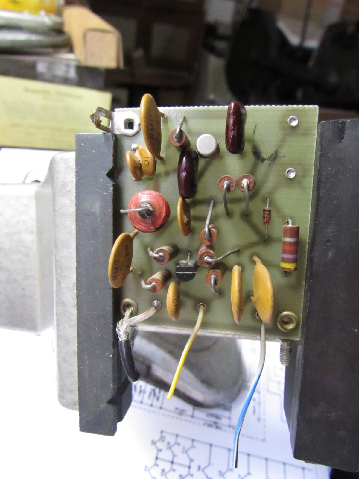
This is the vice grip that I use for my soldered board pieces. It has a swivel that permits pivoting and rotating. Quite handy. Notice the coax, the yellow/ white and the blue/ white wires. Also at the upper right you can see the two points where I de-soldered the leads that connected to the calibration board. Fortunately the traces from these two points did not lift. Re-soldering was a snap.
-
-

I mentioned that the FD-1011 digital read-out which sits outboard, and plugs into the VFO buffer output via a jack in the rear apron, could not see a signal from the 1011D. As it turned out, it had a blown 2N5130 RF input amp, but how did it get blown? I think the above was the culprit. It was soldered as a dead short. How, I have no clue, but the VOM showed complete continuity with ground, and when I lifted the connections, and removed the 1/8th inch jack and checked it, it was still shorted. So I changed it out, re-soldered, checked continuity, and mounted it back onto the rear apron. I then replaced the FD-1011's RF amp in the same manner as I described with the VFO board.
-
-
And here is the result. I now have a working and calibrated digital read-out. On Ten Meter "Low" (28.025 - 28.625 MHz) this device is critical because the resultant frequency after conversion does not come close to the 27 MHz read on the transceiver's actual dial. The "High" band is great, spot on, the the "Low" portion requires the use of the FD-1011. Oh, I suppose I could make a conversion table but that would be rather clumsy.
-
-

In order to remove and replace the jack on the rear apron, I had to remove the power supply board. I also replaced the filter caps while I was at it. BTW, this was how my operating bench sat for a solid month awaiting those transistors. My own post office delayed delivery by about three weeks by failing to leave an attempted delivery notice. But, it came, and everything went together well.
-
-

Well, this about wraps up the restoration and rehabilitation of my Siltronix 1011D Ten Meter station. I do have one thing to add: Drift.
I have heard all the horror stories about the drifty Swans, and this rig is no exception. One of the reasons lies in the fact that it has a very high intermediate frequency, which in turn uses correspondingly high frequency variable tuning RF elements, oscillators, and such. Conventionally, such circuits are kept as low in frequency as possible, usually relegating higher frequency oscillators as xtal controlled, with low frequency VFOs injecting at the mixer stages. Swan doesn't do that. Their receiver IF chains, and as such, the entire RF chain, transmit and receive, are quite high in frequency. While using higher frequencies as the intermediate frequency is great for front end image rejection, heat generated from within the transceiver will really set things off until it stabilizes, which might be after about 30 minutes warm up. However I found that a fan helps maintain temperature regularity, thereby helping to stabilize frequency drift, faster than with no fan.
Normally, such a vent fan draws air out, but the rear aprons of the Swans have very little ventilation. Almost all ventilation comes via the top clam shell half, which is perforated, sides and top. The final is dropped into a cavity which is almost impossible to get to, and air flow is quite restricted. As such, I decided to force air into the rig and let it blow out the sides. I have had any number of folks correct me on FaceBook over this, but I maintain that better cooling with this rig is to blow the air in. At least, it's working for me. Without the fan, during warm up, AF4K identified a 200 Hz drift in the course of one minute's transmission. Have contacted several stations since, with the fan running, no appreciable drift has been noticed after a reasonable warm-up period. The fan in the photo operates on 117vac, and plugs into one of the a.c. outlets on the back of the rig, as does the FD-1011. The fan plugs into the outlet that is switched by the power switch on the radio, so it turns on when the 1011D is powered up.
Another drift-prone point is the VFO switch. Swan incorporated a band switching VFO, separate LC tuning circuits for each band, which means the actual wafer switch to which these VFO connections are made affects the tuning of the band, too. If you slowly turn the band selection switch, listen to the rig's receiver. Man, it's all over the place until the switch is in place. Don't rock the band switch! Change your band, leave the switch alone, and you're golden. A little DeOxit on all these switches and moveable connects is advisable. Once clean, once all screws are tightened, once all moveable items are secure, these rigs are actually quite stable.
Now that the rig is done, I have spent the last week working evening/ late afternoon sporadic openings with good results, most folks I call come back. The receiver is sensitive to a fault! Transmit quality gets compliments. The Shure 444 mic that came with the rig does a great job, and the speech amp really "kicks". The weak 8950 permits about 45 or so watts output PEP on sideband, and about 20 watts on AM. Fine for me, actually. The ANL actually limits noise although voices sound better with the ANL off. But in a pinch, it does save the ears, and signals can be heard. The FD-1011 tracks dead on, on AM and on LSB. USB reads 4 KHz higher, which makes sense.
She's been an adventure, she's fun to use, and she's actually amazingly simple and easy to maintain. In the big scheme of things, there really isn't much to her, she's a very basic gal that seems to age well, and if you understand her characteristics, she'll show you a great time.