All Things Wireless & Letterpress

All Things Wireless & Letterpress

Sunday, December 27, 2015

Dolly.

I thought a might share an article I wrote years ago.  A few regional Ham Radio club journals picked it up.  I think it dates to around 1997.  I just copied and pasted it directly from my old Radio site that I used to use to post my stories.  Publications would pick the stories they wanted from there.  But that was long ago, when I was a free lance writer for the electronics hobby industry.  But this story came to mind recently, and I thought I might re-air it here.  It's a story about a very special triode that I picked up about thirty years ago.

 "Dolly" 

From the Radio Rescuers Journal, entry #2.

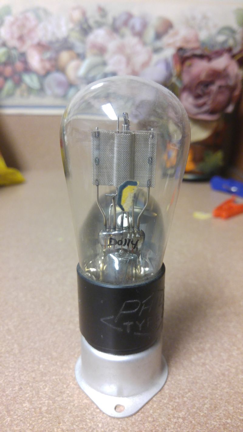
Not too long ago, at the Orlando Hamcation, I happened upon a ballon type '27 triode. Just your garden variety a.c. tube. Probably dated to around 1929. It had lots of dust and some kinda smeary stuff on it, making it look really bad. I offer to pay a buck for it, and the guy behind the table says "sure."  Off I go with my little treasure to hopefully use it to give life to a rather dormant Doerle regen I was reconstructing.

Old glass tubes are a funny sort of device, with a charm all their own. Mostly they are mirrored with a silvery internal coating, and I would be a liar if I told you that I knew what caused it or even what it was.  Just one of those mysteries I choose to retain as a mystery.

Very simple devices they are, little more than a dim lightbulb with extra wire stuffed in to form an anode, filament, an indirectly heated cathode and a gridiron. All this is mounted internally on a single glass pillar, usually bearing the hand written mark of some unknown quality inspector. A cypher of a sort, usually a number or a number-letter combination. Locked in a vacuum of time for the life of that tube. I wonder if they had any idea how long some of those tubes would last?

Well, after coming home, I began to work on cleaning off that tube, using dish washing liquid and a soft cloth. The smeary stuff came off, but the dust had hardened into a thin filmy concrete which took a little elbow grease. "Uhh-ohh", I thought as I began to hand polish off the surface:  " There goes any decal or print on the envelope!" But I consoled myself with the knowledge that at least I would still have that classy silvery stuff, whatever it was.

And then I saw it!

Behind the silver! There was an area in the silver coating that was very thin, exposing the central pillar of the tube. Almost like looking thru a keyhole, the silver framing the view. There, written on the pillar for all to see, a single name.

"Dolly ".

No cypher, no number, no arbitrary letter, but a name! Immediately, this became no ordinary tube! It became a link to a person. I began to wonder who this person was. Did she work part time for Philco to get thru school? Did she fare well thru the Depression just about to befall her? Did she take pride in that tube as she carefully painted the five letters of her name on that tiny, tiny pillar before it was sent in for the envelope and evacuation process ? Am I getting carried away ?

I had a suspicion that of all the '27s in the wide world, THIS one would be among the best performing. It had to, it bore her name. . . and it is.

Remember, whenever you affix your name to something, that something may last well beyond your puny years. Remember too, that the performance or quality of that thing will be forever inextricably linked to you. Whatever you do, do your best.

And Dolly, wherever you are . . .
. . . thanks!

vy 73

The Lafayette Dyna-Com: Part 3, Battery Spacers.

As mentioned in Part 2, the higher power Dyna-Com series utilized what I consider a somewhat unconventional battery pack system.  Let's take a look again at what the manual shows:

It clearly shows, and clearly tells you, to use either twelve 1.2v NiCads, or ten 1.5v AA cells, even to the degree of specifying the actual AA cell!  And .... to the chagrin of many that I can tell by reading the forums....the AA cells simply do not fit!  Not satisfied with just one, I tried three such Dyna-Coms.  No Bueno. Die gehen nichts!  The AA cells do not fit!  Now, if memory serves, the NiCads actually are a tad smaller, and that is literally all that is needed: about 1 - 2 mm length reduction for the entire four column series of batteries.  Take that 1-2mm and divide it by four, and that's all that's needed for each battery to be reduced in length by.  Was there some manufacturing shift in the past 40- odd years that made AA cells a millimeter longer??  One of y'all find out and get back to me, I've gotta move along here.

Before we leave this page in the manual, let's take one more closer look:

Clear enough, right?  

Since in the past, I only had the three watt DC's, I never had to deal with this.  The lower watt DCs used a standard 8-clip AA battery pack ....which also took AA NiCads!  Hmm ....

So, what to do?   I have been picking up Dyna-Com HTs for some years now, and never once have I seen the spacers offered as a featured item along with these units on eBay or other auction venues.  So I have never seen the actual stock item in the flesh.  But the drawing gives me a clue: they appear to actually look like a battery after a sort.  So, here's what I did.  I located an aluminium tube the approximate size of a penlight cell (AA size battery), and then I found a solid aluminium rod that would fit nicely inside of that tube.  I cut the rod and tubing to 3-3/4 inches, the tubing just a touch smaller than the inside rod.  This was the length I arrived at, which is just a bit smaller than two penlight cells end to end.  The measurement proved accurate.  

Any hack saw can be used, I am fortunate to have a mitre saw with a metal cutting blade, so I used this to do my cutting.  I also have a grinding / polishing wheel.  The grinding wheel is fine grit for sharpening hatchet and large knife blades, the polisher is actually a wire brush wheel.  All I wanted was to even up the saw kerfs and bevel the edges.  The wire wheel got a lot of oxidation off the tubing and rod (they were laying in my antenna scrap pile for years!) and smoothed out rough edges.

Soon I had what you see here.  The makings of what I think will be a dandy battery spacer.  All I need is to heat shrink some tubing as a nice looking jacket, and wow, maybe they will look like the actual stock item!  I sorta like going over the top on stuff like this.  Just me.

So here we go!  Ready to slide into the clear plastic battery tube.  They fit quite nicely, with good tension.  Now, for the other two channels holding batteries, I used three AA cells and one AAA battery.  This way I have at least the proper voltage.  The current will be a touch less, I should think, but not enough to make much a difference.  And to be sure, the battery indicator is behaving the same as it did with 18v, and twelve batteries in tow!  

So, there you have it, gang!  Now you, too, can be just that much less dependent upon someone else to make something work.  I particularly like that aspect of DIY.  But then, that's what Homebrewing is all about!  

BTW, thank you for your kind comments on FaceBook!  I know that many hams cringe at the idea of putting CB oriented stuff up on the ham radio FB interest groups, but as an Amateur myself, who is a Tube/ Valve homebrew jockey, totally cw oriented, a Mill op with a J-36, I can understand that.  It's just that I also see the surplus market drying up and parts that were once plentiful and cheap disappear.  It makes precious little sense to me to not take advantage of resources that are still with us, and still affordable, and I place the CB equipment, or at least a lot of it, in the catagory of  "ready resource". Especially these portable rigs.  Talk about fun QRP that you can take with you hiking, hunting, climbing, canoeing, biking, even parachuting (use a bolt-on base loaded whip antenna if you are gonna jump.  The poor telescopic antenna is good for about a 30mph gust.)

A look ahead: A college friend and myself will do an actual road-test and distance check between the three watt DCs, and the 5 watt DCs.  Also, a DIY "Dyna-Charger".  Lafayette made two, one sports a cradle for the Dyna-Coms.  The other does not.  We will explore the construction of the one that does not.  If you can build that, then use your imagination for the cradle-type.  And let me know how you make it, ok?

I am currently in conversation with ICM crystals, Quartz Slab, and am looking to approach a crystal manufacture in Northern Italy to see if I can get a decent price for 29.000 MHz xtal pairs.  These will be expensive.  But I think the expense will be worth it.  But even if these remain on their native Citizens Band, I intend to have a blast with mine!  Maybe talk a couple of the local 2m simplexers to join me.  Heavens!  Could you imagine that!  Hey, it could happen.  Just like we had those late night round table discussions on CB channel 11 back in '69.  It wasn't dumb then ..... we had a few hams that joined us back in those dear, dead, pre 10-4 goodbuddy days!  In fact, guess how I got into Ham Radio to begin with?

-gary // wd4nka.

The Lafayette "Dyna-Com", Part Two

My own personal Dyna-Com arsenal is actually quite a recent acquisition.  I have owned several over the years, but usually they fell prey as trade collateral.  Seems the mystique and attraction is rather widespread and somewhat unexpected. So I would buy them.... only to trade them for something else within about a year.  

I always had an attraction to these "Bricks", and purchased my first one in 1977 (I think.)  The reason was pretty surface: Our local Lafayette, in downtown Orlando, FL., carried crystals for what was then called "Channel 22a".  Back before the FCC opened up 40 CB channels, we had 23 channels.  Channel 23 was used on a shared basis with class C remote control devices.  I recall that channel 23 was almost useless in the Philadelphia area when I lived there, because the traffic signals utilised channel 23.  Or, so was the popular opinion behind the mass of tone signals.  Between CB channel 22 and 23 was 20 KHz, or two channel spaces.  These we referred to as "Channel 22a" or "Channel 22b".  These were shorted out on the channel selector of synthesized CB rigs, so they could not be used.  There were countless schemes describing the magic wire to cut to access these "super secret" channels.  It was just too easy to simply buy the high power Walkie Talkie and insert the "super secret" channel crystals!  And so, that's what I did.  Me and the guys (the guys and I . . . sheesh . . ) would hang out on 22a, much the ire of others from whom we wished deliverance from.

Later in years as a Ham, I purchased a couple Dyna-Com 3Bs on this new medium called "eBay".  I used them when I was on my roof working on my 40m vertical antenna, and needed something to both keep me company up on the roof, and provide a way to shout down to the control op when doing remote adjustments at the antenna feed point.  I always got a kick out of working hand-held portables out in the open. And, sorry, it was more entertaining to listen to the CBers than the diminishing crew on 2m.  In fact, I have as of the past five years seen our local amateur VHF community all but vanish.  The CBers are still having their morning coffee on the air.  What gives, guys?

Just as an aside, the longest distance I ever talked point to point on a hand held unit at any time on any band, was using that very Icom 2AT in the photo.  I used it atop Brasstown Bald's ranger station look-out, and raised Thomasville, GA.  Essentially, I was up in north Georgia almost at the Tennessee line, and I talked down to the Florida Line, spanning the whole state of Georgia from north to south, on one watt, two meter FM simplex.  I have also spoken point to point with parachutists at twenty thousand feet in a free-fall drop. Rigs like the Dyna-Coms are fully capable to perform these same amazing point to point contacts, conditions permitting - of course!

So, let's talk about these devices, generally.

These radios were designed to have similar receiving and transmitting characteristics as Lafayette's CB base units, the Comstats 19, 23mk5 and 6,  25A, 25B, the HB series bases and the Telsats.  They have single conversion superhet receivers utilizing ceramic filters.  Adjacent channel rejection was about the same as the big bases and mobile units.  They had a speech amp circuit Lafayette referred to as "Range Boost", which focused increased audio into the amplitude modulation sideband envelopes. I might call it an early form of speech processing.  It was not simply increased gain.  The Comstats had the Range Boost function as well.  It made quite a difference when copying a 3 watt AM signal through heavy QRM.  

They have provision for external mic, external speaker, external antenna, and external power.  Channel switching is a side panel function.  They carry a battery indicator that would indicate both voltage and signal strength . . . to some degree.  On the lower right of the above photo you can just see the external power and charger jacks.

The two and three watt units carried a battery pack for eight AA cells.  The higher power systems used the whole rear panel of the unit as a battery holder for either ten AA cells or twelve equivalent NiCad batteries.  When Alkaline or any non-NiCad batteries were used, a battery spacer was inserted into one row, as seen in the diagram above.  This served the purpose of keeping the voltage to 15 volts (the rated voltage for the five watt Dyna-coms).  The spacer made it possible to use only two batteries in one of the rows.  NiCad batteries were 1.2v each, so twelve NiCads were used.  More on this later.

There were a few accessories available for these units.  Of course, no thinking person who just dumped fifty or more bucks into a walkie talkie in 1969 would just take her naked into the woods.  No, you had to get that genuine cowhide case.  That really dressed her up, and more: they provided genuine protection!  These were cowhide cases that would themselves cost as much as those walkie talkies were we to purchase them today!  Kenwood was the last company to make cases like these, for their TR2400 HTs.  Those were made by Gucci, believe it or not!  The Dyna-com cases, well . . . not Gucci, but I wish my boots were made like these.  Oh, and bringing up boots: you keep these cases supple with saddler's soap and protected them with Kiwi shoe polish.  Just a hint.

Another accessory that was a must is the power supply.  The units rested in it.  Unlike the stand-up chargers for VHF/ UHF rigs, there are no charging connects at the bottom of these units, so you plugged the charger in at the side mounted charging plug.  You plugged external power into the external power jack provided right next to the charging plug.  Two different plug heads.  Lafayette would tell you that you needed their power supply, but any supply 12 - 15 vdc would work for the 5-watt units, for the 1 - 3 watt units,  no more than 13 vdc.  The higher power units would work at 12v, but much below this starves the system.

You could also get an external speaker and an external mic.  For stateside systems that were channelized by individual xtal pairs, which would include all the Dyna-coms up to the 12 channel types, the external mic used a single mono 1/8" mini phone plug.  This enabled you to use what amounted to a small speaker as a carbon mic.  It's the same mic as the speaker-mic used by the walkie talkie itself.  But you still have to key the PTT (push to talk) on the walkie talkie itself.  You could not key the mic.  I found this next to useless.  Not entirely useless, but next to it.  The 23 and 40 channel systems used the standard four-connector mic plugs so you could plug a regular mobile mic and key by it as with a regular mobile or base unit.  The foreign export models such as the Dyna-Com 3F also came with a standard mobile/ base mic plug.  I wish they were used on all the Dyna-coms, but then these foreign models were AM/FM units.  That may have had a bearing on why they did this.  It could have been contracted by the services that intended to use them, such as law enforcement or military.  Dyna-Coms were not used by military or law enforcement in the US, but rather by private citizens or companies, such as construction companies or marine facilities.

There is a drawback to using a keyed mic.  Your body is figured into the design of these walkie talkies.  You, dear user, become the counterpoise for the antenna!  This means that to make your little unit an effective radiating device, your own body, capacitively coupled to the metal body of the walkie talkie by your holding it, provides the ground it needs to see.  How can you tell?  If you have a working Dyna-Com, turn it on, pull out the antenna to full extension (always!  Whenever you use these, pull that 'tenna all the way out!) and set it on a table.  You will hear the S/N, native to the receiver, fall off as you back away.  When you pick it up, those signals become significantly louder.  That's the way almost all such hand held units work!  Of course, with the external antenna (another accessory!) body contact is not necessary.  Mentioning the external antenna jack, let me say that it is also a 1/8" mini-jack.  Great for audio. Not great for RF.  I found that I needed to build a small patch cord converter with an SO 259 at one end to use my external antenna, which uses RG58-U coax for the antenna feed.  My old Sears 1.5 watt CB HT used an RCA jack, which was still inadequate, but not quite SO inadequate in that actual converter plugs were made for several units out there that also used the RCA jack for RF output.  The Johnson "White Face" Messenger One, to name one.  To my knowledge and in my experience, no such adapter was made using the mini plugs.  I may be wrong.  Such a converter plug is not mentioned in the Lafayette catalog....unless I missed it all these years!

There is also a provision for a PA system.  I still can't figure out that one.  Why a PA system from a walkie talkie?  They are not bull-horns.  But . . . I'm sure some one may have used one at a private party or a bingo game, so sure.  Public Address away!  But for crowd control - I'm still trying to form that mental image.

Let's revisit the battery installation for the five-watt units again.

As mentioned earlier, these sets were designed to take NiCads and AA cells.  There is no mention in the manual that there is a slight difference in cell size between the two battery types.  Yet every 5-watt unit I have ever seen will not fit AA cells as shown in the diagram supplied by the manufacture.  Just to make sure, I checked out the AA cells specified that are still being made!

Specifically the Eveready E-91.  The exact same size as the Dura-cell AA batteries.  No bueno! They absolutely do not fit.  Lafayette, what gives??   Let's take a closer look at that spacer deal shown in the manual:


The spacer is a conductive cylinder, like a short metal rod cut to the size of two AA batteries.  It's purpose is to short the negative end of the battery in series above it to the negative terminal of the battery holder section in which the battery "tube" lies.  Yet this only affects one of the three battery "channels" (the troughs wherin lie the batteries when slid into their holding tubes) !  So this spacer reveals nothing.  We are still stuck with two channels that will not hold the specified AA batteries!  So, here are the solutions I came up with.

I simply made three spacers from aluminium rod about the same diameter of  a penlight cell!  One for each channel.  This way I still had 9 batteries, or 13.5 v.  The rods were actually a tad thin, so I built up the thickness by wrapping masking tape around it to build up the diameter so it fit snugly in the home-made "battery tube", which I made by simply taking a sheet of photocopier transparency film, available at any Office Depot or Office Max, and cutting three strips approx three inches wide and long enough to permit the two ends of the battery series within the tube to make contact.

The tubes are held in place with masking tape.  So far, my cheap home-made tubes seem to be doing the trick.  If anyone out there knows of a source for thin walled tubing that will snugly hold penlight batteries in place, let me know, and I will post it.  The purpose of these tubes is to keep the batteries from moving.  Four batteries in tandem can create an avenue for slippage which will, in turn, create a scratching sound through the speaker.  So the batteries and your spacers need to be held in place.  Obviously, the spacers that I made were short enough to make the remaining three batteries in their respective series physically fit!

Now, I did something else that might be...well....maybe not kosher, but it has worked so far.  Noting the voltage being lower than the 15v these sets were designed for, I replaced my spacers with AAA cells!  I then wrapped tape around them to build up their diameters to snug well into their tubes.  So, now we have 1.5v x 12 = 18v!  What th....?   Yes, friends, that's what I did.  And with no apparent issue.  I will need to pull one or two out and place the spacer in two of the channels, but just to show that it can be done, there you are.  I might recommend one AAA cell and two spacers, to be absolutely "kosher" (my Hebrew background popping in there.  Oi!)

Here is a close-up of the battery tubes, the penlight (AA) batteries, and one of the AAA cells in place with masking tape wrapped around it to secure a snug fit.  And again, while I inserted an AAA cell in all three battery tubes, producing a voltage of 18vdc, the current will be different.  Just a head's up.  All this means is that the power discharge from the two different batteries ( I/R drop) will be different.  What this spells is probably a shorter battery life than if all the batteries were the same.  I do not anticipate this to be significant.  But then, we are making do with what we have on hand: parts for these rigs are not made anymore.  So, use your own judgement regarding mixing batteries and cutting and using spacers.

So, that' it for this installment, gang!  Stay tuned for the Great Road Test!

-gary // wd4nka.


Wednesday, December 23, 2015

The Lafayette Dyna-Com and Other Anectdotes. Part One.


When I went to Junior High (Tredyffrin Eastown Jr. High, fondly referred to as "TE") I became fascinated with the idea of remote electronic communication.  What began as hard-wired intercoms between apartment buildings between friends (these were made from magnetic telephone receivers, which required no batteries) eventually bled over to wireless experiments with spark-plugs and broadcast band table top receivers tuned between stations to copy a crude buzz in the form of a primitive code.  This in turn, bled over to the inevitable: Walkie Talkies.  Specifically: 100mW superregenerative walkie talkies that I picked up from a neighbor kid.  A few improvements were readily apparent over our experimental spark-buzzer: no code was needed, and we could talk almost one whole city block.

These walkie talkies were almost universally placed on CB channel 14 (27.125 MHz).  Their receivers were so wide that almost everything on 26 and 27MHz could be heard at once.  But this was 1968.  Not a whole lot of folks on the Citizens Band back then, thus what we heard were actual conversations, not a mass of heterodynes.  In fact, it was outright entertaining. The only problem was that in time, and without much provocation, these walkie talkies would surreptitiously break.  Like magic. But then, I guess, one contributing factor were our continued experiments.
It was pretty obvious to me that if we wanted to have a range beyond our block, we would need either a bigger antenna or more power.  Ideally both.  What to do?
A bewildering assortment of antenna wires were strung hither and yon, from bedroom window to balcony, across our "court yard", various groundings were explored, all of which helped to extend our range a little bit.  To increase power, best as we could understand the nature of power from a transmitter, we would series up one 9v battery after another. More volts, more power, right?  Burn-up usually happened sometime around 54 volts, as I discovered. All through these experiments, we managed to break the one-block barrier, and talk to a CBer on the next block!  It was during this conversation that I discovered the 54 volt barrier. Wow.  The great DX chase was on! 
My parents were pretty quick to pick up on my radio activities. And it didn't escape them that I was up until midnight listening to my walkie talkie.  It also didn't escape from them my disappointment when my little walkie talkie gave up the ghost.  

Christmas was coming.  Christmas 1968.  The new Holiday Season issue of the Sears Catalog came out.

What I opened up that Christmas Eve was the most amazing Christmas present: a very heavy-metal 1.5 watt Walkie Talkie from Sears!  It had two channels, channel nine and eleven.  Thirteen Transistors!  Wow.  Late Christmas Eve, and on into the wee hours of Christmas Day, I was talking on my new power house.  Mom and Dad had gotten me a power supply so I didn't have to worry about replacing batteries all the time.  The telescopic antenna was HUGE!  It had to be over forty inches.  And the range!  I could be heard all the way down to the end of the street, and . . . beyond!
Mind you, we lived on the middle, or second floor.  I set up my walkie talkie near my bedroom window.  I had a little elevation.  From that telescopic antenna I discovered I was able to talk between one and two miles out. This floored me.  I was using a superheterodyne receiver now, not a superregen, with increased sensitivity, lower noise floor and signal-to-noise ratio, and hugely better adjacent signal rejection.  

All the cold winter, and through the spring and into the summer was I on the air every day after school and weekend evenings.  Our apartment complex custodian, himself a CBer, gave me a mobile antenna sold by Lafayette called the "Tiger Tail", a center loaded CB mobile radiator mounted on, essentially, a metal box with a knob and an SWR meter.  You could literally tune out the reactance right at the feed point.  The neighbor upstairs let me bolt it to his balcony, the highest floor available, the third floor.  With that outside antenna, I managed to work from Wayne/ Devon, over the Old Eagle School Hill, and down into the Von Muehlenberg - King of Prussia area.  That was about eight to ten miles!!  One watt output, radiating from a center loaded quarter wave whip bolted to the steel rail of a balcony seventy five feet from the ground.  Not too shabby!

I was wholly absorbed.  I cannot express the thrill it was to break that one block barrier.  And then, the indescribable rush of working into the next two blocks.  Then working one mile!!  Then three.  Five.  Eight.  One mobile on the Main Line (Route 30) guesstimated he was about ten miles from me once.  I entered that into the log book I was keeping.

I began to notice those other Walkie Talkies in the Lafayette Catalog.  We had an LRE (Lafayette Radio Electronics) at the King of Prussia Mall.  They carried these solid steel and chrome walkie talkies.  One was an amazing 100mW two channel with a tone alarm and superhet receiver, called an HA-73.

Eventually, years later, I would buy one of these, but what really caught my eye among these Lafayette walkie talkies even more was what I considered my next logical step up in my radio endeavors, right there on page 459 in the Lafayette Catalog : the Three Watt, Three Channel Dyna-Com 3.  My 1.5 watt Sears Walkie Talkie was great, don't get me wrong - but the Dyna-com 3 shown in this catalog was a beast!  I just knew that with one of these, I could work my way out to Paoli and Berwyn, a good ten to fifteen miles, with ease, and possibly even all the way down the Main Line to Villa Nova University, almost twenty miles! Especially if I could also get that Range Gain II antenna, also shown in the catalog!!  No telling what horizons I could explore.

Now mind!  I was anything BUT bored with my Sears rig.  It was fantastic. Every night was a new adventure. But it is human nature to want to go just . . . just . . . one more step. To push the envelope.  As such,  I opened up a proclivity from which I suffer to this day, one which has dogged me all my Ham Radio life : just one step more.  One foot higher.  One watt more powerful.  One more QSO.  One more mile.

The Dyna-Com 3B.  This was the Daisy "Red Rider" of Walkie Talkies!  There was a kid out on Old Darby Road that I would be able to reach from time to time, who had one, with a 102" stainless Steel mobile whip mounted on his rain gutter.  It seemed that I could always hear him better than he could hear me, a range of about three miles.  He was considered DX in my log, btw.  I rode my bike over to his house once, carrying my Sears walkie talkie, and saw his Dyna-Com with my own eyes.  I got to hold it.  Wow . . . it was heavier than mine, and my Sears was no light weight. It had an S-meter of sorts.  And like mine, it had a leather case, only his was more robust.  Everything about his Dyna-Com seemed over-the-top.  The chrome and steel body.  The three channels.  The three watts.  The notably longer telescopic whip.  Even the case!

I want you to know that at the time my parents purchased my 1.5 watt Sears walkie talkie (or HT - Handy Talkie), the price tag was about fifty dollars.  That was 1968.  This amounted to one quarter of my dad's weekly take home pay.  That was a lot of money.  Seventy Dollars for a Dyna-com was nigh unto impossible, so I never breathed a word about my wanting a Dyna-Com to them.  I may have been an ignorant kid, but not a stupid kid.  My parents gave me an awesome gift at great sacrifice, and I was determined to be satisfied.  And, really, I was.  Nonetheless, that Lafayette catalog sure was fun to look through, though.  Especially the Walkie Talkie section.

In the 1960s and on into the 70s, Christmas brought forth a whole raft of kids, being gifted with toy walkie talkies.  Almost universally they were on CB channel 14.  At one watt, I found that I was the loud voice the kids were mystified by, and listened out for.  I would greet these kids with a "Merry Christmas", which was quite an exciting thing for them. Over the years, this had come to be quite a tradition with me, to listen in over Christmas Day to Channel 14, to send a Christmas Greeting to the kids with their new walkie talkies. Some of these kids were eventually likewise bitten by the radio "bug" as did I, and they persisted in their radio activity, becoming themselves part of our on-the-air regulars.  Some of these kids, like me, continued to upgrade to the larger walkie talkies.  Some, in the ensuing years, became Hams, just as I did. All had their seed-bed experience using these amazing walkie talkies, and pushing the envelope with them.

Lafayette had quite a run with their Dyna-Com line of  walkie talkies.  They were specifically designed for public service or private/ professional field use, which is why they were so ruggedly built.  They ranged from the 2 watt two channel, up to the the fully featured 5 watt 12 and 23 channel models. There were models available only in certain countries that used FM on 27MHz. All of them built like Panzer tanks. You might notice if you have the catalog,  the hard-hat wearing construction worker, shown on the pages where are the Dyna-com walkie talkies.  That was your clue what sort of environment they were intended for.
These higher watt rigs usually worked on 15 volts, and carried 10 AA cells, or 12 nicad cells.  They had an odd battery "spacer", which took up two AA cell lengths in the holder, for use with Alkaline batters, which was omitted when using Nicads.  The batteries and spacer was slid into plastic tubes which helped to hold the batteries in place, in case they may be prone to wobbling in the rear battery compartment. You could directly recharge the nicads through the charging jack.  The crystals in the 12 channel Dyna-Com were accessed by the front steel panel.  These units were spaciously designed.

As I draw this segment to a close, let me provide a link to download the Dyna-Com 12A owners manual. In later installments I will chronicle in greater detail the Dyna-Com walkie talkies as I go through the paces with both the 3 series and the 12a series.  We will be looking at their set-up, examining and solving the "Battery Dilemna", listening to their audio, doing point to point range tests, and then replicating my own early set up with an external power supply and antenna.  Just to see what these "bricks", as I fondly call them, will do.  At one point I hope to convert these rigs up into the Amateur Ten Meter "AM Window".

My point and purpose in this article, Part One, is to provide a little background as to why I have a special fondness for these hand held marvels, and the significance they played in my having become a Radio Ham.  There is in reality very little on the web regarding the Dyna-Com hand held portables, their practical use or known modifications.  It is my goal to help meet this deficit.

Stay Tuned!

de WD4NKA.


Saturday, November 28, 2015

Ham Radio Horizons: "Building the Fifty Watt Rig", Part 2.

We continue our Educational Review from the Eye of the Printer and Graphic Designer, who also just happens to be a Ham Radio Operator, and who happened to be part of the intended audience of these articles.  We will look at the writing style of the author, the graphics used, the general lay-out of the article and endure some commentary concerning the current state of technical writing from my personal perspective as a former corporate training writer, technical illustrator, and national training director for what was, during my tenure (if you can call anything at the corporate office level "tenure") the largest optical retailing company in the world.

As such . . . yeah, I got a lotta opinions.

Opine No. 1: why don't they write these sorts of articles anymore?  If ever a step by step, one-two-three mentoring piece was ever written that reached out from the pages, took the reader by the hand and actually not only walked him or her through the mechanical process of building a rig to be proud of, but also equipped said reader with the information to academically assess and determine the what and why-for's, this is probably the most exemplary article I have ever read to these ends.  If I still had my training writing team, and we were tasked to create an SOP manual for constructing a widget, this would be our model.  And yes, that is how training curriculii is written, gang.  We borrow examples and massage them.  We hire companies to fill our data banks, and we writers create the links that interconnect the data in such a way that instructs.  Bill Wildenhein, W8YFB (as of 1978) did a marvelous job doing this very thing.  Only, he didn't hire anyone to do anything.  This was his own baby from the get go, and we were fortunate that Mr. Tenney (Skip) had these installments published. 

So, here we go.

I did not see the artist's attribution in these articles, but whoever he or she was, my hat is in my hand.  These were a combination of freehand pen and ink illustration and genuine, old fashioned drafting board layout mechanical drawing.  Nothing was computer generated in this article.  And figure: it was printed in 1978.  Do you know what I was doing in the 70s besides being a novice?  Shooting artwork for a magazine, developing the negs, stripping and pasting and burning offset plates containing this artwork for a local area Orlando magazine (Orlando-land Magazine, to be precise.)  As such, I like to think I know what I am seeing.  This sort of lay-out is called a "duotone", used in magazine publication since the 19th century to great effect.  It makes the page interesting and inviting to read.  The nice thing is that the drawings just happen to be mechanically accurate! What a concept.  An artist that knows what's going on.

I am not a huge fan of the larger formatted magazines, which departed from the older journal sized "almanacs" that was universally used for such publications from the turn of the century up into the mid 1970s.  I believe QST was the first to change over to the large folio sized magazine around 1975.  All the others followed suit.  The smaller magazine was, to me, much more convenient on many levels.  They also seemed more personal, and actually, a bit more authorative.  Just me, I guess.  I grew up on 1930s Red Jacket QSTs and old S-9s that my elmers would dig out of their attics and give to me by the boxes in the 1970s.  I loved them.  I kept a lot of them.  In fact, they were the reasons why I even do these blog installments! Each one was a literary work.  And we can find a fascinating narrative of Ham Radio through the years by doing what we are going right here: reading them and getting a feel for the times, challenges, and technical environment of the average ham in the era in which any particular issue was printed.

Let's take another teckky look at this page: the photo.  It's called a "Half Tone".  The original photo, hopefully a high contrast glossy which photographs well and leaves a great negative, is reduced to dots.  Highlight dots and density dots.  The highlight dots are micro-fine, and appear in the white areas.  The smaller the dot, the whiter the white, but you must always have a dot in there, no matter how white the image field is!  This is how contrast is controlled, and what keeps the printed image from looking like a poor photocopy.  Same goes with the black areas: the density dot is actually a white dot created by the very large halftone dots that eclipse each other.  They space between them is white, from the paper it's printed on, and serves the same purpose as the very fine highlight dot: to balance contrast, and to keep the shaded areas from going full flood black, which looks awful in print....although I have seen this happen with some of the privately published computer printed magazines these days.  I cringe. Oddly enough, ER magazine does a fair job with their imagry, considering the shallow images they have to work with.  They do tend to flood their whites on their covers, but that might be because they use....or used to use....a coloured stock which does not do wonders for contrast.

Remember, would be magazine printers: Contrast.  The three big keys to good printed graphics are 1) - Contrast.  2) - Contrast , and 3) - Contrast.  But never flood your highlights or densities.  Get it?  Got it?  Good.  I can sleep now.

BTW, this is why I stay Letterpress.  And pen and ink renderings.  

The image on the above shown page is actually quite shallow, and the guy that shot the neg went to a 600 line screen to hold what detail he could.  And I say, he deserved a raise.  This was no computer evaluated half-tone, it was done by eye, by densitometer, and by skill.  Another reason why I like old publications.  

Another reason is because I love the movie "The Secret Life of Walter Mitty".  Watch it, fellow commercial dark-room rat!  (if you haven't already.)

Bill the Author lays down simple theory and a bit of math, once again, for the benefit of the reader to understand how and why they are metering the screen and grid of the final.  The approach is classical. "Ethics Rise from Dogma", which means before you task anyone to do anything, you first lay out why!  The Apostle Paul even wrote his Epistles following this paradigm!  Before he tasked the reader to any sort of behavour he laid down chapter after chapter with Doctrine, and provided a link with the word translated "Therefore".  It is a basic writing technique. One I see less and less of these days.

Can't find the meter that reads the scale you need in mA?  You don't have to.  Here, the author teaches the reader how a meter functions and how to build a resistance network based upon the meter's own metrics to indicate the desired scale you want!  Have you ever seen this sort of detail in a construction article before?  I mean, really!  That's why it took three installments to publish this piece!  And the odd thing: as of my last perusal, this article appears nowhere on line, which I think is a crime.  Well . . . it is, now.  As an Educational Review, but it's here, nonetheless.  If you really want this article to have and to hold, contact CQ magazine.  I think they bought out Ham Radio Report, the parent publisher for HRH.  They may have ALL six or so years of HRH.

On page 37, the author walks the the reader through the controls, following the same mode of communication.  Here is also where be begin to see more actual mechanical drawing, and some of this probably came from clip art.

Ever wonder why they call it "clip art"?  Well, glad you asked:

Technical Illustrators draw a lot, but we didn't draw everything.  There were some areas where a lot of repetition of imagery was required. There was really no need to redraw each and every arrow, circle, this thing or that.  Sometimes, people were needed to populate, say, a landscape scene.  We don't care who they are, we just need people.  At one time the engraver engraved each and every man, woman and child on the printed image . . .to be used for one run only!  Early on, when the photographic process began to be used in the 1870s, standardized images began to be cut and pasted into the artwork, and then shot for plating.  Such images were drawn, and later printed, on large sheets that could be easily cut and used in the past-up room.  The Paste up room is where each page of a magazine was laid out, the text on printed paper, the high contrast line are was oriented, &c.  The negatives were shot and "stripped" on a sheet of "goldenrod", UV-proof paper, and set up according to the "paste-up", and the plate for the page or pages were then "burned" and taken to the press-room.  So, repetitive images, normally small elements that feed the whole image, were "clipped" from a sheet and pasted in.  We do this today with clip art books, too.  So, I guess it's pretty obvious where the term comes from, but I thought I might engage in a bit of history as well.  That's why I write these pieces after all.

It also keeps this blog entry an Educational Review.  So, bear with me, ok?

These are pages 38 and 39, each containing what I believe to be a hand rendered bit of artwork.  If it indeed clip work from the paste up room, they had access to clip are that I did not have!  I think what they did was draw the shells, and one contact, which was then duplicated and then pasted all around.  Rapidograph touched up the seams.  We used to do this sort of thing for Orlando - land magazine as well.  I was not present for the printing of this magazine so I don't know for sure, but I do know what technology was available in 1978.  A lot of hand work went into these pages, trust me.  The illustration in the upper right of page 39 has a combination of hatch and stipple shading.  That baby was drawn by Rapidograph.  When I illustrated the training manual for Pearle Vision, Inc., I drew many of these detail images.  In fact, they were kinda fun to do once you got the pencil down.  Stippling is something that is rather cathartic to me.

What was described above is also true here as well.  These are not clip art inserts from the paste-up room, these are hand drawn images, likely executed with old school drafting ages.  The braiding of the coax shown on page 40 (left) is hand rendered.  All the cross hatching and stippling work was likewase drawn in either by Rapidograph pen or mapping pen.  Does anyone do this anymore??  I purposely shot these images such that they can be downloaded and enlarged so you can get the detail!  

You know?  Novices like me needed all the help we could get, and the more realistic the images are, the better chance we had at understanding what was going on!  This was why such lengths were taken in the day, by this publisher, to ensure great visual communication.  Even with our computerised illustrations today, I still detect a certain homogenization that serves to prevent such detail, even though we are capable of off-the-map detail.  Perhaps it's because the artists and designers did not grow up in a truly detailed hand rendered visual environment?  Who knows.  It costs to have excellent artwork made, perhaps that's part of the problem.  I might note that I am only illustrating on the side, and that for my own company, Paper Wren Press.  By profession, I am a Licensed Optician.  Huh . . . what does that say??


Here, we come to the end two pages.  Page 42 features another drawn image showing the critical components as real images of correct proportion.  The accompanying text describes the purpose for wiring these components as such. I can look at these drawings forever.  I might make mention of the tube sockets: there was something we did in the darkroom, which was simply laying a specific screen with a desired dot size over the negative.  This was not the same as half-toning, which indeed uses a dot screen, but the exposure is entirely different, and involves another process.  In screening, we just shot the image by wrote, through the screen.  This gave the effect of "tinting" or "graying" a solid area.  The same was done in the burning process, where we might expose a negative to the UV while burning a plate, with a transparency dot screen under the negative to achieve the same effect, only by direct burn to the plate.  These tube sockets were shaded in the same manner: not by hand, but by an equally arduous process, by screening.  Screening could be a nightmare in the stripping room where the negs are opaqued and laid out on the goldenrod for plating.

On last observation: page 43.  Yeah, Palomar paid for that add to appear on that page.  And it is fairly interesting from a graphics standpoint.  This is a duo-tone, with no screening, although I might have pushed for screening the colour in the actual product image.  See how sharply contrasting the red shading is in the product image?  They do that to add effect: it's a graphics way of underlining, or bold-facing.  To attract attention to a specific area.  I think it looks positively ugly, but hey....even when I did this professionally, the voice of the darkroom seldom was heard in the front room where such decisions were made.  We just bit our lips and did what the work order commanded.  Yeah....our lips bled a lot.

Well, here ya go.  Another installment and graphical assessment of a great and what I opine to be a Classic Article, from a very good author, printed in a very special Magazine, Ham Radio Horizons.

The last installment covering the last section, Part 3, will be forthcoming.  And folks, especially you hams so inclined: Novice Rig Round-up happens in February.  Go to our FaceBook Page for details if you'd like to participate, and possibly even build this very transmitter!!

73, es CUL - de wd4nka


Thursday, November 26, 2015

Revisiting the "Fun-Mitter", a Goof Proof RF Project from 1981

Note: these photos were uploaded in large format.  To enlarge, click on the images, and download from the link by right clicking on the link image and selecting  "save image as". You should be able to at least double the image size.

I'm always a little nervous whenever something comes my way that claims to be "goof proof".  I am the one goof they didn't consider. When Mark Oman, WA0RBR wrote this article, a whole generation of QRP enthusiasts was just getting off the ground.  This was a group that preferred simplicity, something that could be made from readily available parts, something that could be made in a couple hours.  At the time, even the "simple" receiver and transmitter projects in the newly formatted ARRL handbook tended to be quite involved to build.  The DC receiver was the home brew receiver of choice, regen receivers were not even on the radar.  It was a time quite different from today in some respects, yet not all that different in others.

In the era of the 1980s, Radio Shack still somewhat appealed to hams and home-brewers.  They actually carried broadcast caps, all sorts of chokes, and the ever popular 40673 dual gate mosFETs, MPF-102s, 2n3904s and 2n222a type transistors and FETs.  And as well, a selection of power transistors, such as are used here.  And while these power transistors may not be available through RS,  they are still available via cross referencing NPI products, and I am sure, other manufactures as well.  The ones I located on line averaged about five dollars per transistor, all such transistors benefiting by heat sink mounting.

Heat sink mounting is advised in this article published by '73.  The photos show "Dyna Labels" in use for labeling.  Gosh, remember the Dyna-Label guns that punched them?  I always considered them along the lines of an over-stuffed chair on a front porch.  But they served the purpose!

These transmitters ran on 24 volts, which the author explains is easier to use to obtain 5 watts input.  I noticed in the power supply schematic that LM-317 is not included in the shopping list of parts, yet is clearly shown on the schematic.  It is a linear voltage regulator, available today, which handles an adjustable range of voltages from 3 - 40v.  Of course, two 12-vdc lantern batteries will do the trick, and probably last a number of hours.

Notice the handy transmit receive switch!  The front panel sports a VXO.  You could probably rubber about 1.5 kc out of the xtal.  Now, when we say "rubber", know it means from the xtal frequency up or from the marked frequency and down.  VXOs are rarely a spread range going from one side to the other.  It can be done, with a combination L and C, both variable, but usually the VXO is provided just in case you find yourself at zero beat to a signal, you can "slide to the side" a little, to be heard.

As the "Fun-Ceiver" did a few months later, this article provides an actual size foil side pc board layout so the builder could purchase the copper clad board, the Sodium Ferric Chloride, both of which Radio Shack sold, and make a pc board right there in the shack.  However, most just used plain ol' Perf Board.

The last page shows the inside physical layout, which is amazingly spacious. Here, you can see the heat sinks, which are recommended by the author, and were not available at Radio Shack.  Today we can get these items from Digi-Key or Mouser, probably even at Amazon.com.  The transistor finals (RS 2038) are obsolete and difficult to cross reference.  I might suggest a 2n3553, which carries a 7w dissipation spec, and is also an NPN type.  The RS 2033, also NPN, can be replaced by an NTE-123AP.  It might even be replaced by a 2n2222a.

Try one out for Novice Rig Round-Up this coming February!  Let us know how you fare!

-73 es CUL, de gary / wd4nka


Revisiting another Home Brew Classic: the One Transistor Rig for 40 meters.

For this classic, we step back a few years further to April of 1978.  The magazine featuring this article was Ham Radio Horizons, singularly the best magazine ever printed for beginners, novices, and the Not-So-Novice.  "HRH" was the daughter publication of Ham Radio Report, and had a very respectable authorship.  Jim Fisk, Skip Tenney, Nagle, Orr, and more of this ilk of writers all had a contributory hand in authorship. This particular article was co written by Ed Marriner,  W6BLZ and John Merideth, K5GXR.  It's a shortie, only a couple pages.

The best way to view these images is to click on it, and then save the image from the linked location.  You should be able to enlarge the image considerably.

The project itself appears to have begun as a curiosity.  Looking over the schematic, I might conclude the "curiosity" must have had something to do with how few parts one can assemble and still have a respectable transmitter!  It seems to be a Xtal Pierce, keyed at the collector, and inductively coupled to the outside world through an Amidon ferrite toroidial inductor, a T-97 type.  Of course, a traditional hand-wound output tank would do, really.

This rig has the feel of the famous (or alternately, "infamous") QSL-40, which was another very spartan, bare-bones single element transmitter dating to 1938.  Whereas the QSL-40 made use of the then two year old 6L6G beam power tetrode, this one takes advantage of a transistor designed for television service, the 2n3553.  Oddly enough, I still have a couple of these transistors. 

I am very curious how these little rigs sounded!  The author(s) recommended an old car battery and trickle charge arrangement to power this little 2.5 watt marvel.  My suspicion this rig has considerable current flow.  Figure about three watts output at 12.6 vdc - probably a loaded average of 250 - 300 mA at key-down.  Definitely a battery burner.  

You probably will not tear up 7050.  But it might be fun for Novice Rig Round-Up this February!  After all, that is the collective group to which this article was aimed: the Novice Home-brewer of 1978.  Which included . . . me!  What fun building our own gear was.  And while I did not build this particular transmitter (I was still working on my 6AG7-6L6G MOPA!) - it was articles like these that kept our interest and excitement with Amateur Radio whetted.  We learnt early that the most satisfying contact is a Home Brew contact!

This concludes this little jaunt down memory lane.  I am hoping soon to post the matching transmitter to the recently posted "Fun-Ceiver".  

73 es CUL, de gary // wd4nka.

Blast from the Past Revisited: the Fun-ceiver! (from '73 magazine, July 1981)

Opening note: to view enlarged images, click on the photos.  Save image from the link location by right-clicking and selecting "save image as".  These photos download at approximately 50%, and can be doubled in size on your computer.  I use Irfanview as my go-to viewer.

1981 was a pretty good year for projects, really.  At least for '73 magazine.  Along with this featured article by Mark Oman, WA0RBR, '73 magazine also covered a tube regen and matching transmitter, breaking an almost twenty year silence on such "hollow state" technology!  And indeed, such an article did engender it's share of criticism.  In this blog installment, however, we will review an equally fascinating project, only this one is a classic of another genre: solid state!

In 1981 when this article came out, I was living up in Jacksonville, my first time living away from my home town of Winter Park, Florida.  I was a broke, newly licensed Dispensing Optician at the ripe age of 26.  The last thing that I could do was pop off a couple hundred bucks for a small QRP rig. I was living an a sub-let condo that did not permit an outside HF antenna.  I had my trusty Kenwood TS-520SE with me, and to be sure, I did eventually put a disguised antenna up, but I also wanted something far more portable to take with me to the beach or at least to the St. Johns River where I could sit and watch the big transport ships roll into port with their holds loaded down with Hyundai and Toyota automobiles.  There was a park on the campus of J.U. where I could set up on a picnic bench, toss up a wire, and work some QRP . . . or just listen in on the band.

The Fun-Ceiver shown above seemed to be right up my alley.  Very low parts count and what parts this receiver required were readily available at the local Radio Shack up in Regency Square, near the Pearle Vision Center where I worked.

This article is amazingly concise and very detailed, especially for the builder of 1981.  The only thing I wish was that the author include substitutes for the active components, which are referred to only by their Radio Shack designations.  The same is true with the "Fun-Mitter", which will be the next installment.  But thankfully, unlike 1981, we have the Internet and Google.  All these references can be cross-referenced.
For our purposes with this particular article, the active components used are the 3n211/ 40673 Dual Gate mosFET, the MPF-102, and the 741 op amp. I purposely digitized these scans of the article such that they can be clicked on and enlarged.  Of interest here is the mixer circuit itself, here being operated such as to produce an audio difference (Direct Conversion) - can also be used at the RF level as an RF mixer with only a couple component changes.  I will discuss this down-range.

You might notice these pages are worn and quite marked upon with my own construction notes from countless replications and slight revisions.  I found the variable diode set up for main tuning in this article was very drifty, so I replaced them with a conventional tuning cap which helped considerably.  While the modified Radio Shack 10uH chokes were fine, I opted to wind my own from scratch using powdered iron cores from the local surplus.  Later I used T-50-2 and T-50-6 Amidon Toroids. 

Looking back on this project, I have to note that in the midst of it's "bottom line" minimalist approach, the author included an active 741 op amp cw filter!  In fact, one of the reasons why I am revisiting this article is because I plan to use this filter in a project for Novice Rig Round-Up!  Googling these op-amp active filters, I find that several can be cascaded to achieve differing levels of filtering.  This is something I found to be characteristic about the circuits shown in this article: they can not only be easily duplicated, but also cascaded with little or no modification.  For instance, the mixer/ local oscillator in this project can be operated not only to produce an audio difference frequency, but also a much higher radio frequency differences.  I made a 40 meter down converter using this very circuit with one capacitor change in the output, substituting a 100pF SM cap.  The local oscillator was a xtal pierce 2n2222a circuit.  This RF mixer fed, in turn, a duplicate mixer using a VFO local oscillator, producing an audio difference output. (a BFO/ Product detector.)

A superhet in it's most basic of elemental form.  Simply from cascading what basically amounts to this receiver.

A decade or so later, this very circuit became the experimental down-converters for my prototype Regenerodyne.  They worked fabulously feeding a regenerative detector which had more than enough Q to select the untuned output of one of these mixers, perfect to tune about a 500 kHz wide "IF Window", which became the heart and soul of the Regenerodyne.  All thanks to this little 3n211 mixer and an ultra simple xtal LO!   Once I "road tested" the regen-converter scheme, I built down converters using a 6J7 or 6K7 pentode and a 6C5 xtal LO....just to keep things "all hollow state" - but rest assured, these little minimalist mixers shown in this article as a Direct Conversion mixer, and used my myself at RF, work very well for the purpose, in fact, possibly with a lower S/N level!  Today we live in a post-3n211 world, which in itself has become about as scarce and expensive as many tubes/ valves!  Even the then-popular CA3028 vhf mixer IC which found use in many HF DC receivers is become unobtainum.  But the devices that substitute for them these days are far more silent, thus if you are interested in trying these mixer circuits, try out these modern substitutes!

Radio Shack sold Sodium Ferrichloride in sufficient strength to safely etch a circuit board.  Some of the surviving Radio Shacks still around, most of which are franchises, may still carry boards and etchant.  "Instructibles" on Line also has articles on how to produce your own.  The above page shows the foil side of both the receiver and the 741 op amp filter.  I etched the board for the receiver, although I never did make the filter.  Later I built successive receivers and modified down converters on regular perfboard and sometimes even drilled masonite!  Just about any insulating surface works, even plexiglass!

The author chose not to include an audio board or an audio circuit, though one can be easly made around an LM-386, which is what I recommend.  The suggested audio section for this project was Radio Shack's amplified speaker, which is what I also used, and what the photo in this article shows.  And to be sure, it was quite effective.  Making your own LM386 audio final does allow the builder to shape the audio, add bass, and any level of gain desired.  So for the builder of today, I'd say take advantage of the web and google the many simple audio circuits out there.  Later I will post one to this blog as well.

That's it.  Next project posted will be the "Fun-Mitter" from Febuary 1981's '73 magazine, which was actually the first in this series.  I posted the receiver first because I actually built it.  I never did make the transmitter, but we will give it a once-over as well, together.

de gary // wd4nka


Saturday, October 24, 2015

Vintage QSL Cards: The Printing of the W9AC Card!

This is a QSL card.  QSL is part of the traditional "Q" signals used in radio telegraphy and telephony for over one hundred years.  It was used aboard the Titanic when MGY Marconi operator Phillips told the Telefunken operator aboard the Frankfurt to clear off: ( "QRT  QRT  -  in QSO Cape Race" - which means, literally "pull your plug, or 'get off the air', I am talking to Cape Race" . . . often interpreted as "shut up".  It did not mean that, but that's another story for another day....

This is a QSL card.  QSL means "Confirmation of Contact", and has been in use for about as long as the Q-signals have been round as a means of confirming, or proving a contact. When a person is contacted, and they request a QSL card . . . perhaps to put up on their wall or QSL board (ham radio shacks used to be literally wall papered with QSL cards!) - or perhaps to send off to a contest bureau for the Worked All States or Worked All Continents awards, which proved you indeed did contact that rare station in the middle of the Indian Ocean.

The data contained on the QSL card usually has standard radio log book information, such as the date and time of contact, the frequency of the contact - or where on the different Amateur Radio Bands did this contact take place, the quality of the signal, the signal strength, the name of the operator sending the QSL card, the call sign of the respondent, almost always printed on the card, and the call of the recipient - hopefully the fella you contacted will send one back to you in the return mail.

In the older cards of the 1920s and 1930s, a brief description of the transmitter, receiver, and aerial (or antenna) was usually given, largely because all was home built.  As time went on, this became less and less a feature as more and more rigs were being purchased as a manufactured product.

The older cards are become quite collectible, and surprisingly, NON-hams even purchase these from eBay, Craigs List, and other places where they turn up for sale.  They have become a category for post card collectors and Philatelists who specialize in these sorts of postal ephemera.

Much after World War Two, and especially much after 1950, QSL cards became a mass produced product, but in the 1920s and 40s, and most of the 40s, they were very frequently printed by the local printer.  More often than not, the local printed used the same press upon which he printed bill heads, stationery, business cards and other "job" work - the Trusty Letterpress.  Often, these were hand-set cards using what the printer had in the shop as far as typemetal and wood fonts.  Others had images made into "cuts", copper or zinc dies produced from photo images (a process that dates back to the 1870s).  Some even carved wood cuts and lino cuts.  

Offset printing became much more common during the fifties and sixties, owing to it's very fast production time and relatively simple plate making systems which could produced in-house for multiple colour runs.  Still later, digital printing became increasingly popular.  
Today, such conformation is normally made via the internet, but still there are those who prefer 'snail mail' QSL cards.  I among them!  And along with me, several folks that still traffic the airwaves using traditional Amateur Radio equipment, tube-type gear that dates back 50, 60, sometimes even 90 years : Morse Code is experiencing a surge of popularity, especially hand sent code on traditional keys which are still being manufactured!

Paul, who's card is under discussion in this blog entry,  is among this group, and when he found out that I had a letterpress shop and knew a bit about the Old Cards and their designs, he contacted me to print a couple hundred for him.  We went over several 1920s and 30s designs, taking elements from several, and produced a design that is very traditional to, say, 1930.

One challenge in the design we chose had to do with the original wooden font used for the call.  We really liked the out-sized serifs and almost 19th-century newspaper headline look.  But . . . the font does not exist anymore!  Many of the American Type Founder's fonts have been digitally reproduced, but not this one!  In fact, it's name, "Foster", has been re-branded!  Fortunately, one of my best resources for this sort of research is my trusty . . . somewhat dissected . . . ATF Specimen Book, circa 1915.  We found a positive match:


While the complete alphabet was not shown, enough of the letters were found on the four sample pages that I could piece together elements of character structure so as to sort of reverse engineer the whole alphabet.  This was accomplished on my faithful and trust vector IDE: Macromedia FreeHand MX.    What is particular unique looking over these sample paragraphs are the figure '4' and the lower case 'g'.  There was more than enough to cobble together the call "W9AC".

I opted not to use process green, which was my original plan.  Paul wanted a vintage feel.  Now, when these cards were new, the whites were vibrant, the blacks were clear and crisp, the green was deep and fresh.  In time, these things mellow . . . as do we all . . . and so we chose a soft buff card stock, process black, and for the call, I would custom mix the ink.  No charge to Paul, however, normally custom mixing carries a fee.  I do this by eye and by colour wheel.  While I do not use the Pantone System, I do get help in printing ink proportions from a Pantone Swatch book.  As such, we came up with a great green that edged on the border of olive.  Just enough to suggest a vintage feel.

Yes, fellow Letterpress Practitioners: those are Dave's Ink In Tubes.  I love tubed inks, they just plain last longer!  Higher initial cost, but having just tossed out several 5 lb cans of canned inks that I spent good money for owing to having dried out - especially the rubber based, for some reason - in the long run the tubes are cheaper.  Save yourself and your clients some bucks!  That is, of course, unless you have so much business that you go through 5 lb cans regularly.


Here are the two dies.  The top photo is the text block, process black.  Font chosen was one made popular by the NY Times back in the 1920s (methinks!) - Times Roman, or better known as "Times New Roman".  It's not new, and was available in foundry metal from ATF for most of the 20th Century.  It is traditional, and from a personal point of view, it's easier to read than Century School Book, another common text font.

This is an "overlay impression", printed on a transparency.  This is the preliminary set up for the first run, the black text.  Under this transparency I can slide the card stock to position it using the impression printed on the transparency as a guide.  Then the transparency is removed, wiped down, and used again at another time for another impression.  In this case, the call sign.

There are about twenty-five such oil ports that must be filled before a day's run.  As old as my press is, it runs smoothe as silk.  First we oil her up, then we apply ink to the ink disc. Then turn on the press to spread the ink.  Then comes the platen packing, then the dies are inserted, the rollers leveled, the platen packing adjusted. Then trial impressions are printed on the transparency to establish and set the cards to be printed. Once all the above is done, then we can get to printing!

Here she is, all packed, inked, and ready to run!  The stock, of course, has been pre-cut at the shop's  "bindery", which is located in Orange City, the next burg over.  

All told, it took about six hours to print both colours.  It took about three hours to re-create the call-letter font, Add this to the week - to  week and a half  delivery time for the dies and paper.  The whole process takes, usually, about three weeks.

I thought I might share the video that I made during the printing of this card.  It pretty much takes you from beginning to end of the process.  From time to time you might catch a few shots of my station, itself pretty vintage in and of itself.  In fact, at the end you might pick up a little code in the background. 


That's about it for this installment!  I hope it's been informative and perhaps a bit entertaining.  Probably nowhere is the Letterpress intertwined with Wireless than in the printing of Radio Stationery.  It is part of what we do at the Paper Wren, and if anyone is interested in having their very own genuine 1920s - 30s - 40s QSL cards printed for their Station - not copies, but originals - please contact me at paperwrenpress@gmail.com, or my personal account at wd4nka@aim.com.

Oh, and before I forget: the photos of Paul's card at the top showed the Crane Lettra run.  I made these cards on two types of card stock: on was hard, friendly to fountain pens, the other friendly to ball point, and which leaves that very nice depression, or "deboss" in the paper.  If one is going for the most traditional, the harder stock would be preferable.

-gary // the Paper Wren  (Paper Wren Press)

Update: I have had several inquiries regarding the printing of Letterpress QSL cards.  I thought I might share what we have arrived at for pricing.

First, we are using two types of paper.  The first is the more authentic light buff hard surface 90 lb card stock.  This paper is fountain pen and typewriter friendly, which would have been used in the 1920s through 1950s, for the reason that fountain pens were the pen type used before the day of the Ball Point. Many hams chose to type, rather than write out their cards, thus the card stock used had to be able to physically fit into the typewriter!  If you fall in this category, this would be the paper we recommend.

The second type is the type you see in the photos in this blog entry: Crane Lettra, 110lb "Pearl".  This paper is what we use for our fine press announcements and business cards.  It is a very velvety, dense stock that leaves that nice indentation, or "deboss" which you see in the photos.  It really leaves a stunning image!  This paper will cause free-flow ink ( fountain pen or calligraphy dip pens) to bleed, however it can handle ball point pens quite nicely, and can even be photo imaged. It may, however, be a tad thick for the trusty Remington or Royal ( typewriters ).  But if you want a stunning card that can ONLY be produced via the ancient Letterpress, this is the stock to get.  It comes in Arctic White (very bright), Pearl (which is an off white, the most commonly used) and Ecru (which is a light amber-honey)  This paper has the distinction of being the same stock Crane sells to the U.S. Bureau of Engraving and Printing - sans silk fibres - for currency.  It is 100% cotton.

Prices for 250 two colour, single sided cards:  

with hard stock, $150.00  plus $6.00 shipping.
with Crane Lettra, $200.00 plus $6.00 shipping.

I do take PayPal, which adds $3.00 to the order. 

Turnaround time averages three weeks.  This is owing to the time it takes to have the printing dies made and the paper shipped in.

Yes, this is a LOT more expensive than your regular process cards which are either offset printed or digitally printed, but I might invite those interested to Google "Letterpress" and check out the prices that post card sized two colour items are normally charged, which is usually twice to four times higher.  I have reduced my normal fees for the Amateur Radio Community for QSL cards and other Radio oriented custom orders.  Letterpress is one of the two most labour intensive - and beautiful - printing methods on the planet.